Intravenous drip monitoring method and related intravenous drip monitoring system

a monitoring system and intravenous technology, applied in the field of intravenous drip can solve the problems of insufficient precision of intravenous drip monitoring, high cost of conventional intravenous drip monitoring methods and related intravenous drip monitoring systems, and poor effect, so as to achieve low cost and high efficiency

Inactive Publication Date: 2011-06-16
PRIMAX ELECTRONICS LTD
View PDF10 Cites 78 Cited by
  • Summary
  • Abstract
  • Description
  • Claims
  • Application Information

AI Technical Summary

Benefits of technology

[0008]Briefly summarized, the intravenous drip monitoring method and the related intravenous drip monitoring system disclosed by the present invention are capable of precisely monitoring dripping conditions of an intravenous drip in order to send corresponding warning messages in accordance with different dripping conditions, and the intravenous drip monitoring method and the related intravenous drip monitoring system disclosed by the present invention have advantages of high efficiency and low cost.

Problems solved by technology

However, the conventional intravenous drip monitoring methods and related intravenous drip monitoring systems cost higher and the effect thereof is not very good.
For example, the conventional intravenous drip monitoring methods and related intravenous drip monitoring systems can not precisely monitor a dripping condition of an intravenous drip in order to send corresponding warning messages in accordance with different dripping conditions.

Method used


Image

  • Intravenous drip monitoring method and related intravenous drip monitoring system
  • Intravenous drip monitoring method and related intravenous drip monitoring system
  • Intravenous drip monitoring method and related intravenous drip monitoring system

Examples


Embodiment Construction

[0029]Certain terms are used throughout the following description and the claims to refer to particular system components. As one skilled in the art will appreciate, manufacturers may refer to a component by different names. This document does not intend to distinguish between components that differ in name but not function. In the following discussion and in the claims, the terms “include”, “including”, “comprise”, and “comprising” are used in an open-ended fashion, and thus should be interpreted to mean “including, but not limited to . . . ”. The terms “couple” and “coupled” are intended to mean either an indirect or a direct electrical connection. Thus, if a first device couples to a second device, that connection may be through a direct electrical connection, or through an indirect electrical connection via other devices and connections.

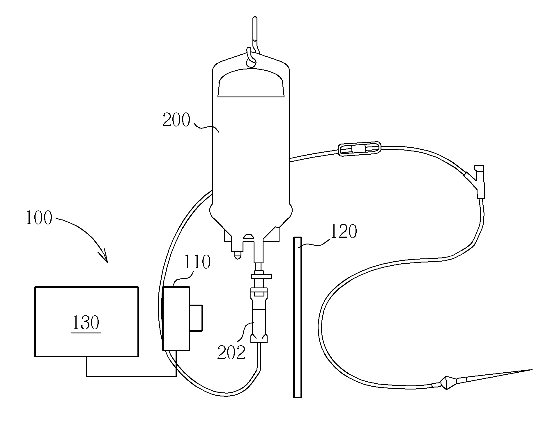
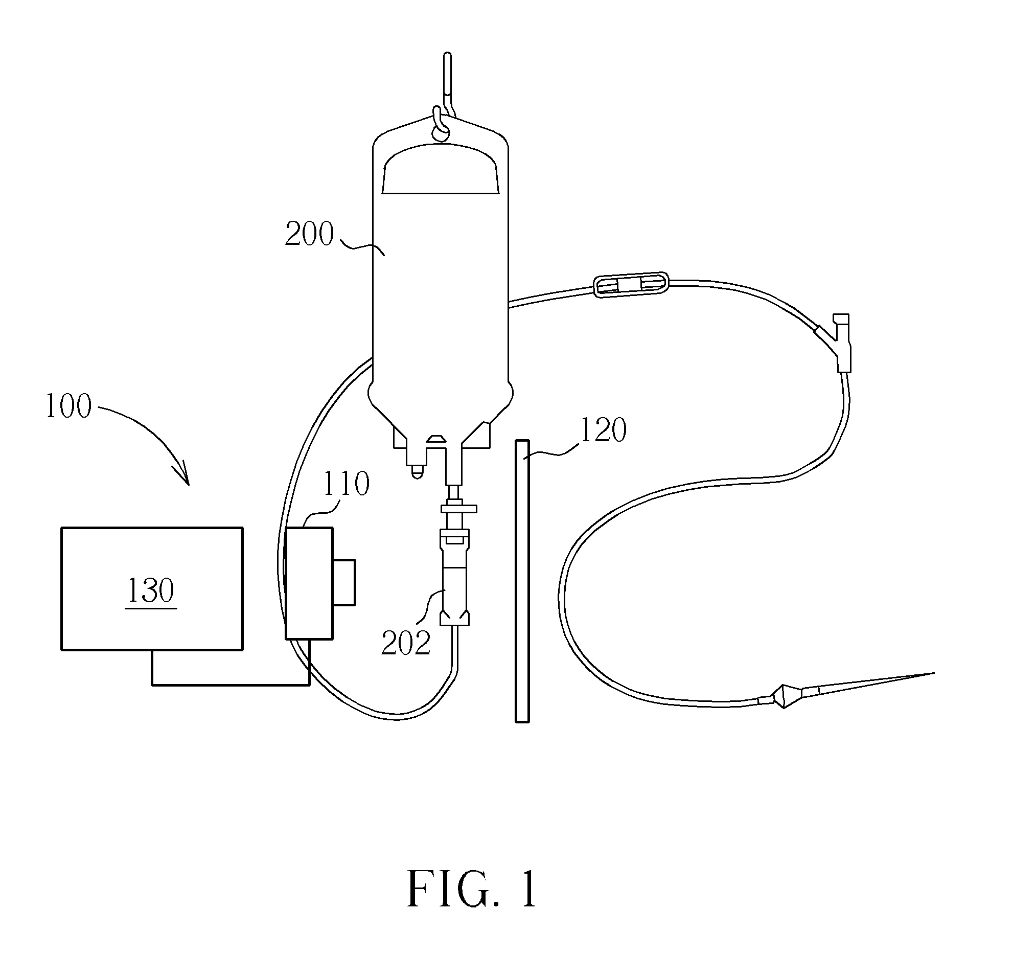
[0030]Please refer to FIG. 1. FIG. 1 shows a simplified block diagram of an intravenous drip monitoring system 100 in accordance with an embodim...


PUM


Abstract

The present invention provides an intravenous drip monitoring method and related intravenous drip monitoring system. The intravenous drip monitoring method comprises: providing a background color as a background of a flow regulating device of an intravenous drip; obtaining a plurality of frames in the flow regulating device of the intravenous drip in accordance of a frame rate; performing an image processing operation on the plurality of frames to obtain brightness variations generated by motion drips in the flow regulating device; utilizing the brightness variations generated by the motion drips in the flow regulating device to detect a dropping frequency of the intravenous drip in a first detecting area of the flow regulating device; and utilizing the brightness variations generated by the motion drips in the flow regulating device to detect a liquid horizontal height of the flow regulating device in a second detecting area of the flow regulating device.

Description

BACKGROUND OF THE INVENTION[0001]1. Field of the Invention[0002]The present invention relates to an intravenous drip monitoring method and a related intravenous drip monitoring system, and more particularly, to an intravenous drip monitoring method and a related intravenous drip monitoring system capable of precisely monitoring dripping conditions of an intravenous drip in order to send corresponding warning messages in accordance with different dripping conditions, and the intravenous drip monitoring method and the related intravenous drip monitoring system disclosed by the present invention have advantages of high efficiency and low cost.[0003]2. Description of the Prior Art[0004]In general, the conventional intravenous drip monitoring methods and related intravenous drip monitoring systems use sensors and measuring circuit to realize the intravenous drip monitoring function. However, the conventional intravenous drip monitoring methods and related intravenous drip monitoring syst...

Claims


Application Information

Patent Timeline
Patent Type & Authority Applications(United States)
IPC IPC(8): A61M5/14
CPCA61M5/1689A61M2205/3306A61M2205/18A61M5/36
Inventor CHENG, TING-YUAN
Owner PRIMAX ELECTRONICS LTD
Why Eureka
Try Eureka