
Hydraulic Circuit

a technology of hydraulic circuits and actuators, applied in fluid couplings, clutches, servomotors, etc., can solve problems such as affecting the performance of the combined actuator, and the flow supply of one combined actuator is inadequa

Inactive Publication Date: 2011-06-23
DEERE & CO
View PDF13 Cites 6 Cited by
  • Summary
  • Abstract
  • Description
  • Claims
  • Application Information

AI Technical Summary

Benefits of technology

[0004]Accordingly, an object of this invention is to provide a simple hydraulic circuit which achieves multiple priority levels for actuators.
[0005]This and other objects are achieved by the present invention, wherein According to the invention a hydraulic circuit of the type specified in the introductory part is embodied in such a way that for controlling the supply priority levels the supply lines of the second and third actuators are connected via a connecting line and a load pressure-controlled priority valve is arranged between the hydraulic pump and the connecting line in the supply line to the third actuator and flow-reducing means are arranged in the supply line to the second actuator, the connecting line furthermore comprising means which prohibit a flow from the second supply line in the direction of the third supply line. Under normal supply conditions of the overall system a flow delivered by the hydraulic pump is in each case able to pass, unimpeded or unrestricted, via the first supply line to the first actuator, via the priority valve, the connecting line and the second supply line to the second actuator and via the priority valve and the third supply line to the third actuator. In the event of a supply shortfall of the overall system, the priority valve closes owing to the connection to the load pressure lines and prevents or reduces a flow flowing through the priority valve to the second and third actuators. At the same time the flow through the second supply line is led via the flow-reducer, a flow via the connecting line being prohibited by the means located there. The second actuator therefore continues to be hydraulically supplied, albeit with a restricted flow, irrespective of the position of the priority valve, even if the priority valve should be fully closed. In the event of a supply shortfall of the overall system, therefore, a minimum supply is delivered to the second actuator with a defined flow via the flow-reducer. This allows a build-up of pressure for the second actuator and ensures its minimum function. With increasing closure of the priority valve, the third actuator is supplied with an ever smaller flow, whereas the first actuator continues to be supplied at maximum flow. Owing to the flow-reducer, a higher supply priority attaches to the first actuator than to the second actuator. The second actuator moreover enjoys a higher supply priority than the third actuator, since a minimum flow for the second supply line is ensured even if the priority valve should be fully closed. Three priority levels are therefore established using just one priority valve. The flow-reducer can be preset so that a minimum flow to the second actuator is guaranteed, whilst at the same time ensuring that in no operating state can a supply shortfall of the first actuator occur due to a flow running off via the second supply line. A hydraulic circuit is thereby created, which compared to corresponding solutions known in the prior art has a smaller overall volume and lower component costs.

Problems solved by technology

In the event of a supply shortfall of the overall system, however, this may mean that one of the combined actuators experiences an inadequate flow supply and therefore fails.
This is particularly detrimental when it is a actuator which should enjoy an actually higher priority of supply than a actuator combined in the same priority level.

Method used


Image

  • Hydraulic Circuit
  • Hydraulic Circuit
  • Hydraulic Circuit

Examples


Embodiment Construction

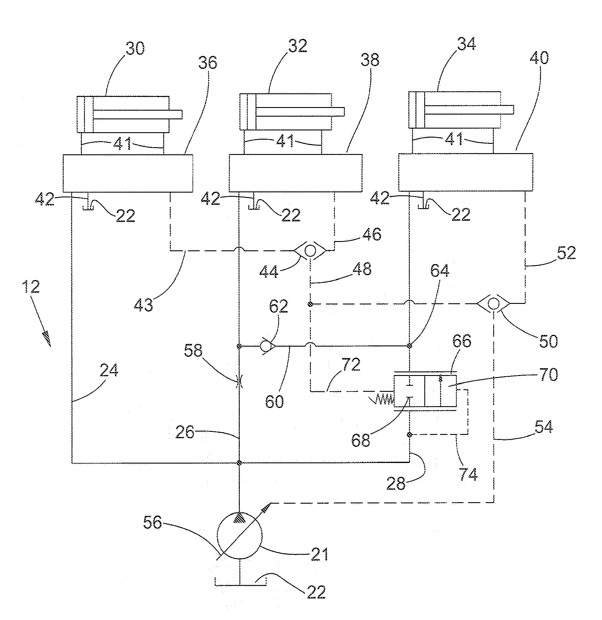
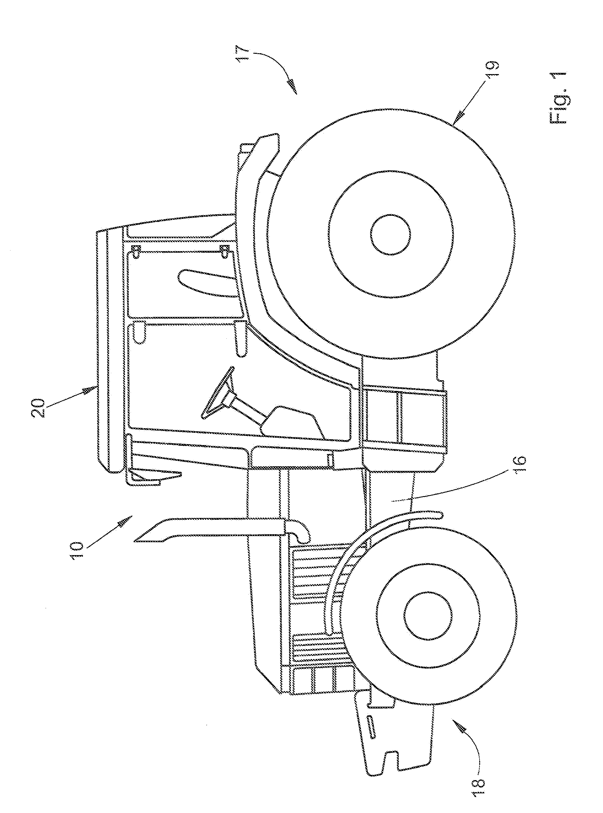
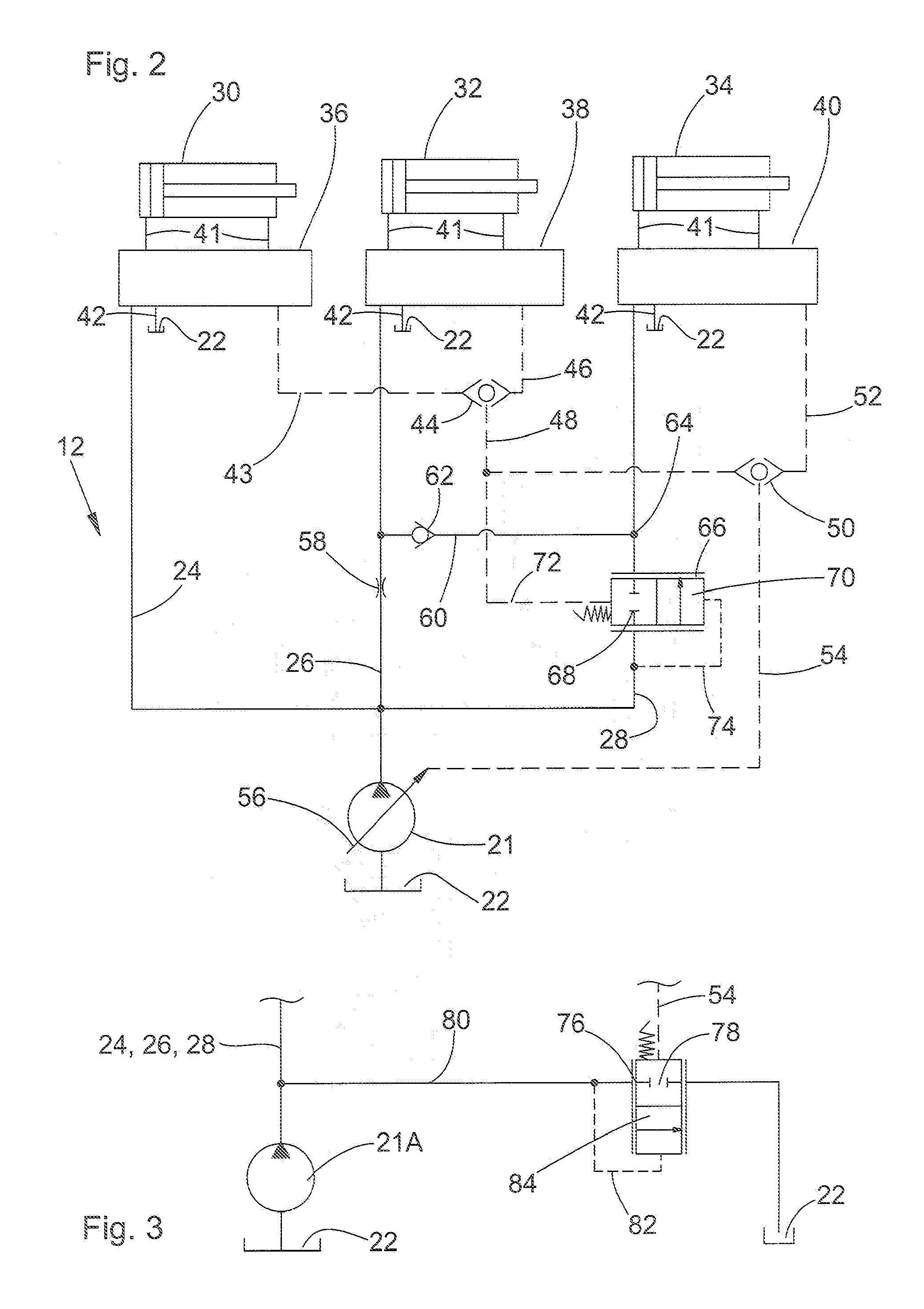
[0020]FIG. 1 shows an agricultural vehicle 10 in the form of a tractor, which includes the hydraulic circuit 12 as shown in FIGS. 2 and 3. The hydraulic circuits shown in FIGS. 2 and 3 are described merely by way of example in connection with a tractor and may also be similarly used in other agricultural vehicles, such as harvesters, agricultural chemical applicators, planting and sowing machines, and also in construction and forestry machines.

[0021]The vehicle 10 includes a frame 16, on which, for example on a rear area 17, a three-point hitch (not shown) with lifting gear for the operation of attachments or implements (not shown) is arranged. A three-point hitch may similarly also be arranged on a front area of the vehicle 10. A plurality of hydraulic actuators are mounted on the vehicle 10, including a lift cylinder which is part of the three-point hitch. The lift cylinder is supplied with hydraulic fluid from a hydraulic circuit 12 shown in FIGS. 2 and 3. The hydraulic circuit 1...


PUM


Abstract

A hydraulic circuit includes a pump and at least a first, second and third actuator, supplied on demand by the pump via respective load pressure lines. Each actuator is connected to the pump by a respective control valve and supply line. A first, second and third supply priorities are assigned respectively to the first, second and third actuators. In order to safeguard priority of the actuators, and to control the supply priority levels, the supply lines of the second and third actuators are connected to each other via a connecting line, and a load pressure-controlled priority valve is arranged between the pump and the connecting line in the supply line to the third actuator. Also, a flow-reducer is placed in the supply line to the second actuator). The connecting line also includes a check valve which prohibits flow from the second supply line to the third supply line.

Description

FIELD OF THE INVENTION[0001]The present invention relates to a hydraulic circuit having a hydraulic pump and at least a first, second and third actuators, supplied on demand by the hydraulic pump via respective load pressure lines.BACKGROUND OF THE INVENTION[0002]It is known to provide hydraulic systems with load pressure-dependent supplies for individual hydraulic actuators, for agricultural vehicles such as agricultural tractors, for example, but also in harvesters and construction and forestry machines. Such systems, also known as load sensing systems, can be operated both with constant-delivery pumps and with variable-delivery pumps having a regulated volumetric delivery rate. Where constant-delivery pumps are used, a load pressure-dependent supply is achieved in that a constant volumetric delivery rate is evacuated via an evacuation line as a function of the load pressure. Variable-delivery pumps on the other hand can be directly operated as a function of the load pressure. Ano...

Claims


Application Information

Patent Timeline
Patent Type & Authority Applications(United States)
IPC IPC(8): F15B11/16
CPCF15B11/055F15B11/162F15B11/165F15B2211/20546F15B2211/781F15B2211/413F15B2211/41509F15B2211/428F15B2211/253
Inventor PETERS, JOSEF
Owner DEERE & CO
Learn More