Hydraulic assembly

A hydraulic component and hydraulic technology, applied in fluid pressure actuators, agricultural machinery, servo motors, etc., can solve problems such as insufficient volume flow supply

A hydraulic component and hydraulic technology, applied in fluid pressure actuators, agricultural machinery, servo motors, etc., can solve problems such as insufficient volume flow supply

CN101994725AInactive Publication Date: 2011-03-30DEERE & CO

Image

  • Hydraulic assembly
  • Hydraulic assembly
  • Hydraulic assembly

Examples


Embodiment Construction

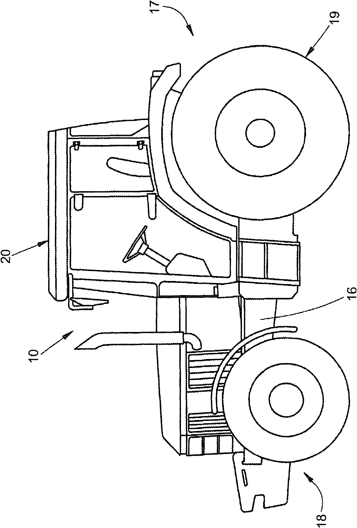
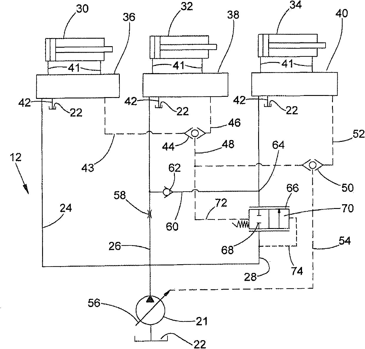
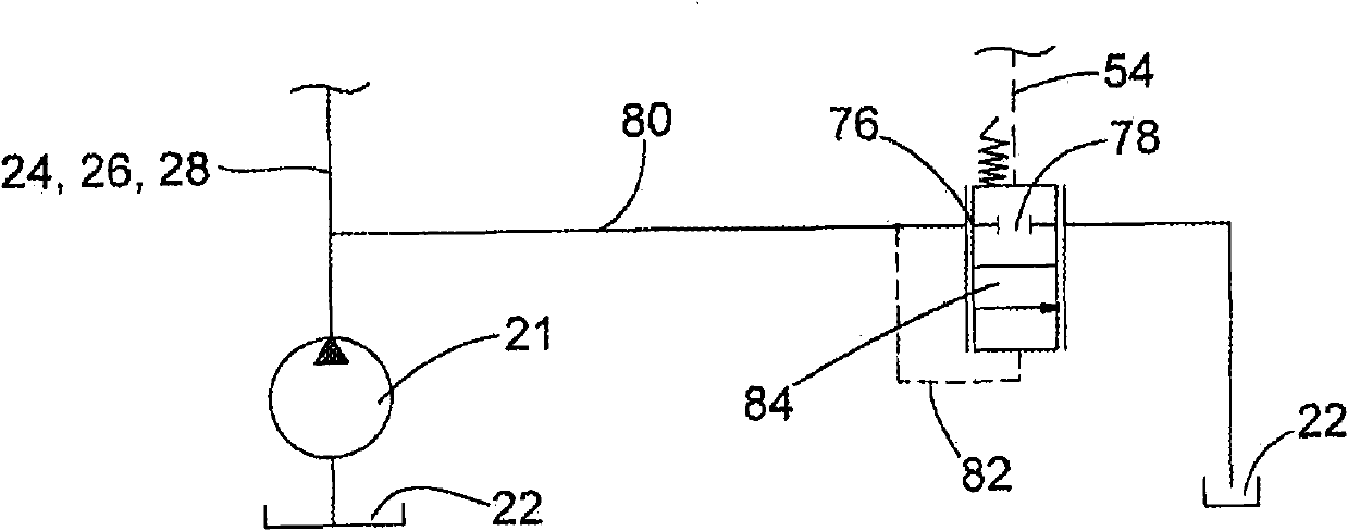
[0022] figure 1 Shown is an agricultural vehicle 10 in the form of a tractor or tractor comprising a figure 2 and image 3 The hydraulic assembly 12 according to the invention. exist figure 2 and image 3 The hydraulic components schematically shown in are only exemplarily described in connection with a tractor and can be used in the same way in other agricultural vehicles (such as harvesting machines, plant protection machines, planting and sowing machines), but can also be used in Used in construction and forestry machinery.

[0023] The vehicle 10 includes a frame 16 on which a three-point hitch (not shown) is arranged, for example in a rear area 17 , with a lifting mechanism for operating a suspended implement or a power implement (not shown). The three-point traction device can also be arranged in the same manner in the front area of ​​the vehicle 10 . The lifting mechanism arranged on the three-point hitch is supplied as one of a plurality of hydraulic consumers ...


PUM


Abstract

The present invention relates to a hydraulic assembly, including a hydraulic pump and at least a first, second and third consumption devices, each of which is hydraulically connected with a hydraulic pump in parallel through its supply line by at least one control valve, the first consumption device is endowed with a first priority level, the second consumption device is endowed with a second priority level following the first priority level, and the third consumption device is endowed with a third priority level following the second priority level. In order to provide low-cost priorities for the consumption devices, supply lines of the second and third consumption devices are connected through a connection line for controlling supply priority levels assigned to controls, a load pressure-controlled priority valve is arranged between the hydraulic pump and the connection line in the supply line of the third consumption device, and a volume flow reducing element is arranged in the supply line of the second consumption device, furthermore, the connection line is provided with a blocking unit for blocking volume flow from the second supply line to the third supply line.

Description

technical field [0001] The invention relates to a hydraulic unit with a hydraulic pump and at least a first, a second and a third consumer (Verbraucher) supplied by the hydraulic pump in a demand-controlled (bedarfsgesteuert) manner via corresponding load pressure lines (Lastdruckleitung) (hydraulische Anordnung), in which each consumer is hydraulically connected in parallel with a hydraulic pump via at least one control valve (Steuerventil) via its own supply line (Versorgungsleitung), and the first consumer is assigned a first-stage supply priority A supply priority of the second level subordinate to the first level is assigned to the second consumer, and a supply priority of the third level subordinate to the second level is assigned to the third consumer. Background technique [0002] In agricultural (landwirtschafilichen) vehicles, such as in agricultural tractors or tractors, but also in hydraulic systems in harvesting machines and construction and forestry machines,...

Claims


Application Information

Patent Timeline
30 Mar 2011
Publication
CN101994725A
IPC
F15B11/16; A01B63/10
CPC
F15B11/165; F15B11/055; F15B2211/781; F15B2211/413; F15B11/162; F15B2211/253; F15B2211/428; F15B2211/41509
Inventors
J·彼得斯