Water treatment device and water treatment method utilizing flue gas waste heat

A water treatment device and flue gas waste heat technology, which is applied in seawater treatment, water/sewage treatment, biological water/sewage treatment, etc., can solve the problems of affecting desulfurization reaction and increasing water consumption of desulfurization process, so as to improve desulfurization efficiency and promote The effect of improving dust removal efficiency and saving water for desulfurization

Inactive Publication Date: 2016-12-14
DATANG ENVIRONMENT IND GRP
View PDF6 Cites 6 Cited by
  • Summary
  • Abstract
  • Description
  • Claims
  • Application Information

AI Technical Summary

Problems solved by technology

At present, the flue gas of most coal-fired power plants enters the desulfurization tower for desulfurization after dust removal treatment. Since the optimal reaction temperature for desulfurization is 40-50°C, and the flue gas at the entrance of the desulfurization tower of most power plants reaches above 120°C, it not only affects desulfurization At the same time, due to the high flue gas temperature, the water consumption of the desulfurization process increases

Method used


Image

  • Water treatment device and water treatment method utilizing flue gas waste heat

Examples


Embodiment 1

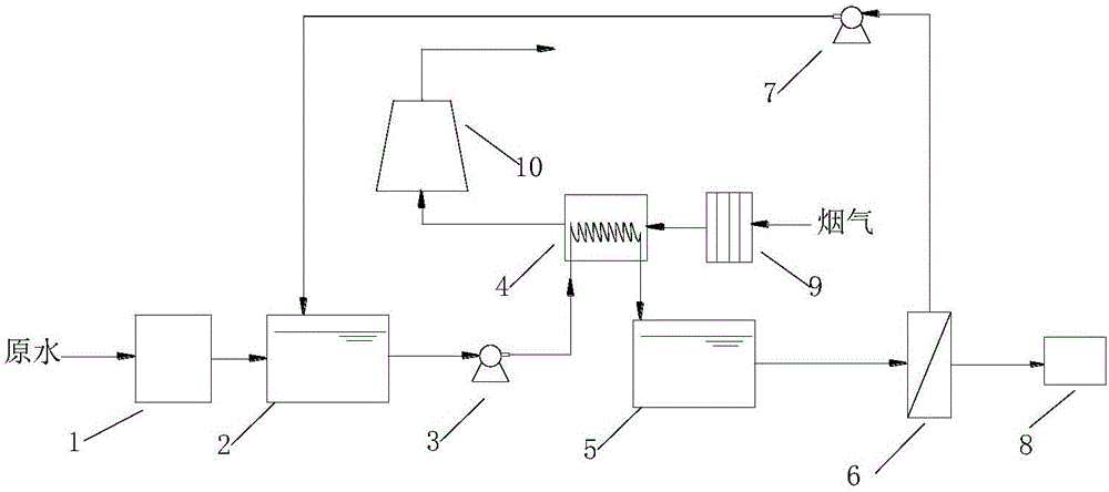
[0032] Example 1, such as figure 1 As shown, a water treatment device using flue gas waste heat in an embodiment of the present invention includes a pretreatment device 1, a regulating tank 2, a first water pump 3, a heat exchanger 4, an intermediate pool 5, a membrane distillation device 6, a second Water pump 7, water production tank 8, dust collector 9 and desulfurization tower 10.

[0033] The raw water to be treated enters the water inlet of the pretreatment device 1, the water outlet of the pretreatment device 1 is connected to the water inlet of the regulating tank 2, and the water outlet of the regulating tank 2 passes the water inlet of the first water pump 3 and the heat exchanger 4 The water outlet end of the heat exchanger 4 is connected with the water inlet end of the intermediate pool 5 .

[0034] The heat exchanger 4 is a single-stage heat exchanger, which is arranged before the flue gas inlet of the desulfurization tower 10, and the flue gas enters the flue ga...

Embodiment 2

[0047] Embodiment 2 is different from Embodiment 1 in that the heat exchanger 4 is a two-stage heat exchanger, including a high-temperature heat exchanger and a low-temperature heat exchanger, wherein the high-temperature heat exchanger is arranged at the flue gas inlet of the dust collector 9 Previously, the low-temperature heat exchanger was set before the flue gas inlet of the desulfurization tower 10, and the flue gas entered the flue gas inlet of the high-temperature heat exchanger, and the flue gas outlet of the high-temperature heat exchanger was connected to the flue gas inlet of the dust collector 9, and the dust collector 9 The flue gas outlet of the low temperature heat exchanger is connected to the flue gas inlet of the low temperature heat exchanger, and the flue gas outlet of the low temperature heat exchanger is connected to the flue gas inlet of the desulfurization tower 10.

[0048] Taking a coal-fired power plant in Northwest China (1 600MW) as an example, the...


PUM


Abstract

The invention discloses a water treatment device utilizing flue gas waste heat. Raw water enters a pretreatment device, the water outlet end of the pretreatment device is connected with the water inlet end of a regulation tank, the water outlet end of the regulation tank is connected with the water inlet end of a heat exchanger, and the water outlet end of the heat exchanger is connected with the water inlet end of a middle water tank. The heat exchanger is located in front of a flue gas inlet of a desulfurizing tower, flue gas enters a flue gas inlet of a dust remover, a flue gas outlet of the dust remover is connected with a flue gas inlet of the heat exchanger, and a flue gas outlet of the heat exchanger is connected with the flue gas inlet of the desulfurizing tower. The water inlet end of a second water pump is connected with the water outlet end of the middle water tank, the water outlet end is connected with the water inlet end of a membrane distillation device, and the water producing end of the membrane distillation device is connected with a produced water tank. The invention further provides a water treatment method utilizing flue gas waste heat. The water treatment device has the advantages that power plant waste heat utilization and a membrane distillation process are combined, the flue gas before desulfurizing is adopted as a heat source of a membrane distillation water treatment system, the flue gas waste heat is fully utilized while the membrane distillation water treatment process is completed, the flue gas temperature of a desulfurizing system is reduced, and the water consumption for desulfurizing can be remarkably decreased.

Description

technical field [0001] The invention relates to the technical field of energy saving and environmental protection, in particular to a water treatment device and a water treatment method utilizing waste heat of flue gas. Background technique [0002] Membrane distillation (MD) technology is a high-efficiency hydrophobic membrane separation technology. It controls the temperature of wastewater and uses the vapor pressure difference on both sides of the membrane as the driving force for mass transfer to realize the process of wastewater concentration and pure water recovery. MD technology and traditional Compared with membrane separation technology, it has many advantages, such as extremely high interception efficiency for salt, nearly 100% interception efficiency for most non-volatile substances, low requirements for influent water quality, and mild operating conditions (no high-pressure equipment is required) , Easy operation and maintenance, less prone to membrane fouling an...

Claims


Application Information

Patent Timeline
Patent Type & Authority Applications(China)
IPC IPC(8): C02F9/14C02F1/16F23J15/02F28D1/047
CPCF23J15/022F28D1/0477C02F1/16C02F9/00C02F1/28C02F1/001C02F1/52C02F3/00C02F1/72C02F2103/08F23J2215/20
Inventor 刘海洋江澄宇薛同来齐勇郭永红孟磊郭清温
Owner DATANG ENVIRONMENT IND GRP
Why Eureka
Try Eureka