Self-Propelled Surface Milling Machine with Electrical Mill Roll Drive

a self-propelled, surface milling machine technology, applied in the direction of driving means, applications, roads, etc., can solve the problems of dust formation by the exiting cooling air, the cooling method that does not apply to the mobile surface milling machine, and the inability to meet the requirements of most applications, etc., to achieve no rotor loss, no intensive cooling of the rotor

Inactive Publication Date: 2011-10-13
LIEBHERR COMPONENTS BIBERACH GMBH
View PDF10 Cites 6 Cited by
  • Summary
  • Abstract
  • Description
  • Claims
  • Application Information

AI Technical Summary

Benefits of technology

[0028]Specifically if the motor is frequently operated at rpm significantly below its nominal rotation speed the conveying effect of such ventilation wheels driven by the motor shaft is no longer sufficient to cool the rotor. In one advantageous embodiment of the invention at least one ventilation wheel that can be driven by a fan motor independently from the rotor shaft may also be provided alternatively or in addition to said ventilation wheels located on the rotor shaft.
[0029]Alternativ...

Problems solved by technology

Having such encapsulated electric drives within the mill roll thermal problems will arise because heat generated in the gear and in the motor will not sufficiently be discharged.
However, these known methods of cooling do not apply to mobile surface milling machines such as Surface Miners, asphalt-milling machines and the like due to reasons of dust incorporation which may be caused by a mill roll operating in or on the soil.
Moreover, depending on the soil at the operational site, heavy formation and resuspension of dust may be caused by strong flow of air that exits the motor, which might not...

Method used


Image

  • Self-Propelled Surface Milling Machine with Electrical Mill Roll Drive
  • Self-Propelled Surface Milling Machine with Electrical Mill Roll Drive
  • Self-Propelled Surface Milling Machine with Electrical Mill Roll Drive

Examples


Embodiment Construction

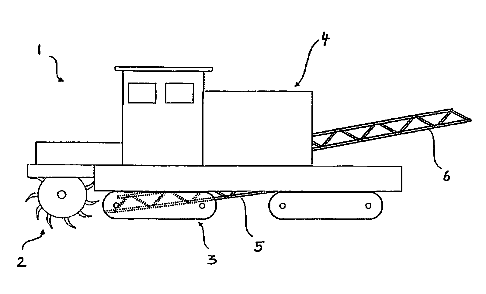
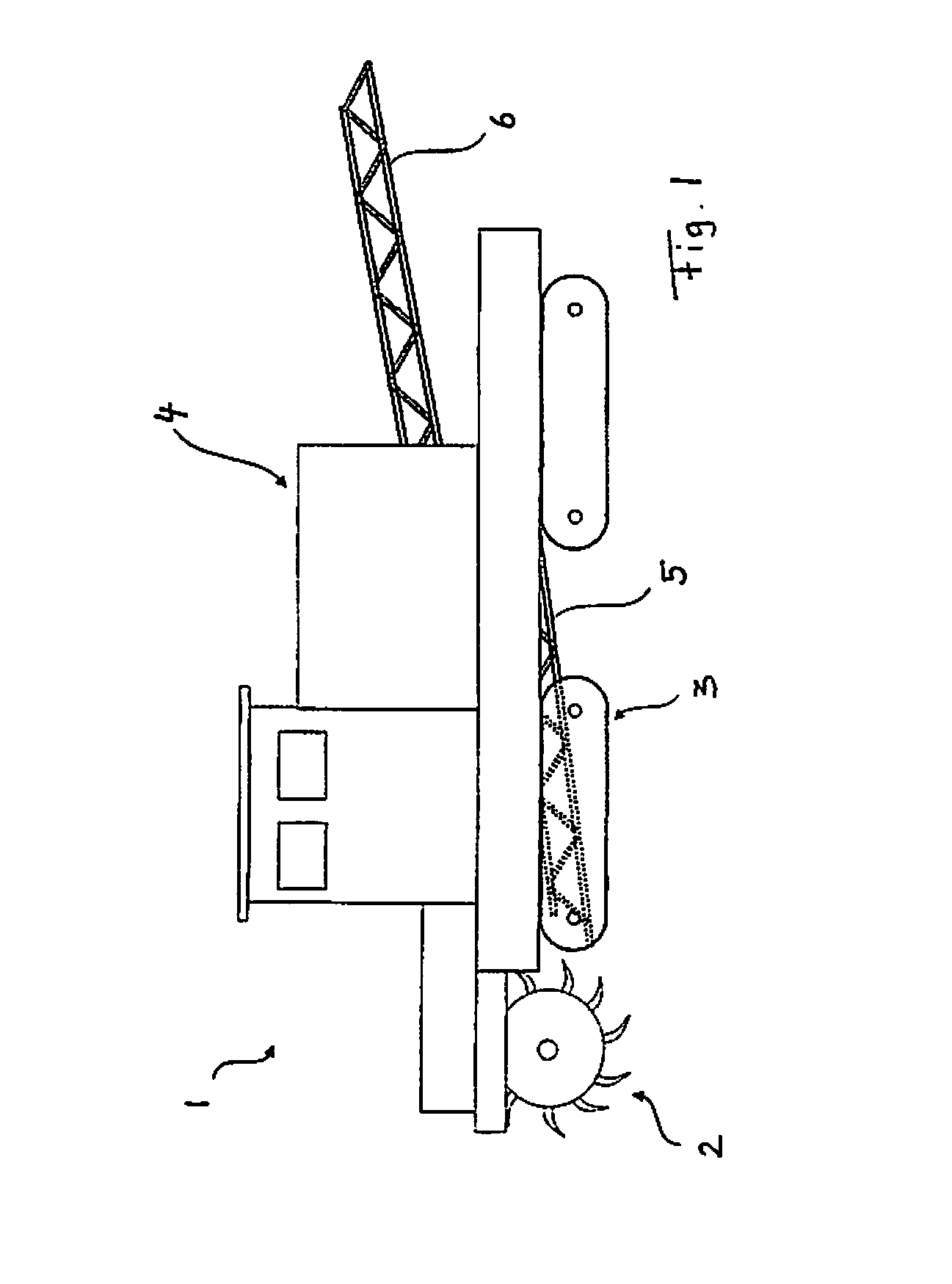
[0036]FIG. 1 shows a self-propelled surface milling machine such as a Surface Miner or asphalt milling machine, the main working unit thereof being a mill roll 2 which is rotationally drivable about a horizontal axle, the circumference of the former being equipped with milling tools suitable to crush a soil or asphalt layer in a milling action. Thereby, the surface milling machine 1 is continuously advanced by means of caterpillars 3 so that said mill roll 2 experiences continuous feed motion. Machine body 4 for which said caterpillars 3 provide mobile support on the ground and support of said mill roll 2 furthermore comprises conveying means for eliminating milled material. The milled material derived from the mill roll will then be transferred to an receiving conveyor 5 passing the milled material to a loading conveyor 6 for transfer of crushed material, for example, to a truck. Said receiving and loading conveyors 5 and 6 may, for instance, be designed as conveyor belt systems.

[0...


PUM


Abstract

The present invention relates to a self-propelled surface milling machine, preferably in the form of an asphalt-milling machine, snow-milling machine or Surface Miner, having a mill roll which is drivable about a rotational axis, and a mill roll drive comprising an electrical motor which is accommodated within the mill roll, wherein stator and rotor of the electrical motor are accommodated within a dust and air-tightly sealed motor housing. It will be suggested to associate a cooling device comprising a closed circuit liquid cooling system to the electrical motor located within the milling roll body. Due to the high heat capacity of a suitable coolant, such as oil or mixed water and glycol small volume flows and hence small conduit cross sections will be sufficient. On the other hand, any incorporation of dust into the mill-roll drive as well as any formation of dust by discharge air can be avoided by the closed form of the circuit liquid cooling system.

Description

BACKGROUND OF THE INVENTION[0001]The present invention relates to a self-propelled surface milling machine, preferably in the form of an asphalt-milling machine, snow-milling machine or Surface Miner, having a mill roll which is drivable about a rotational axis, and a mill roll drive comprising at least one electrical motor which is accommodated within the mill roll, wherein stator and rotor of the electrical motor are accommodated within a dust and air-tightly sealed motor housing.[0002]Surface milling machines are continually self-propelled working machines which, with the aid of a rotating roll, crush a layer of asphalt or soil or the like by milling and which commonly continuously proceed with the aid of caterpillars to force the roll into the milling goods. In doing this said roll forms the main operational unit requiring high energy and thus is in need of an appropriate drive. In this regard DE 10 2007 007 996 B4 suggests a diesel-electric drive, wherein the milling roll of a ...

Claims


Application Information

Patent Timeline
IPC IPC(8): B02C23/00
CPCE01C23/088E21C31/02E01H5/098
Inventor GRANER, KLAUSLIS, JOHANN
Owner LIEBHERR COMPONENTS BIBERACH GMBH
Why Eureka
Try Eureka