Portable, hydraulic, direct force, readout apparatus

a technology of direct force and readout apparatus, applied in the field of direct force measurement, can solve the problems of cumbersome folding and unfolding, require calibration, etc., and achieve the effect of high simplified

Inactive Publication Date: 2011-06-23
SHEEKS OLIVER P
View PDF5 Cites 4 Cited by
  • Summary
  • Abstract
  • Description
  • Claims
  • Application Information

AI Technical Summary

Problems solved by technology

The presently available apparatuses are platform scales which are not handy or typically of the bladder type which are cumbersome to fold and unfold and require calibration for their use.

Method used


Image

  • Portable, hydraulic, direct force, readout apparatus
  • Portable, hydraulic, direct force, readout apparatus
  • Portable, hydraulic, direct force, readout apparatus

Examples


Embodiment Construction

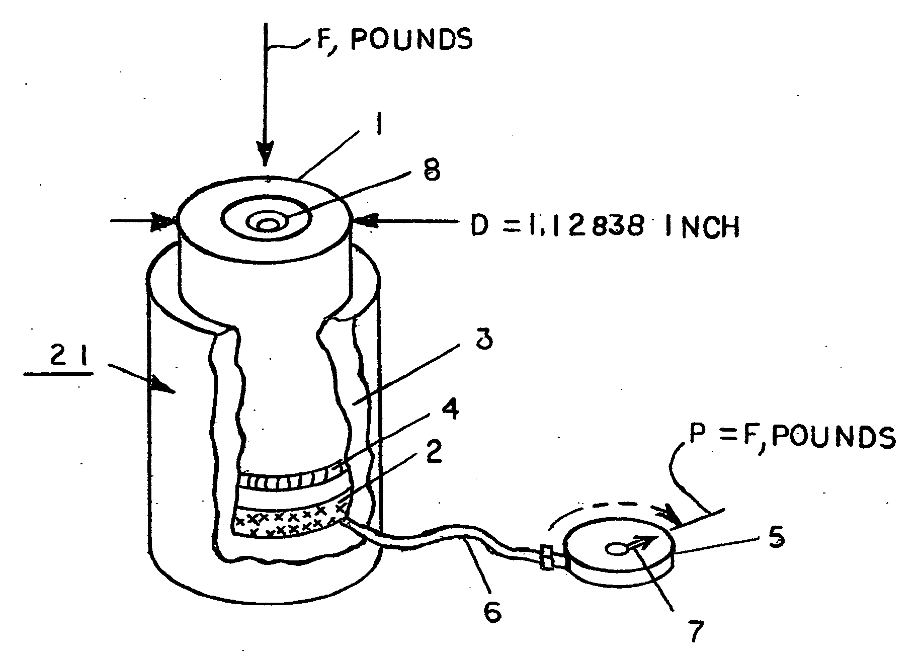
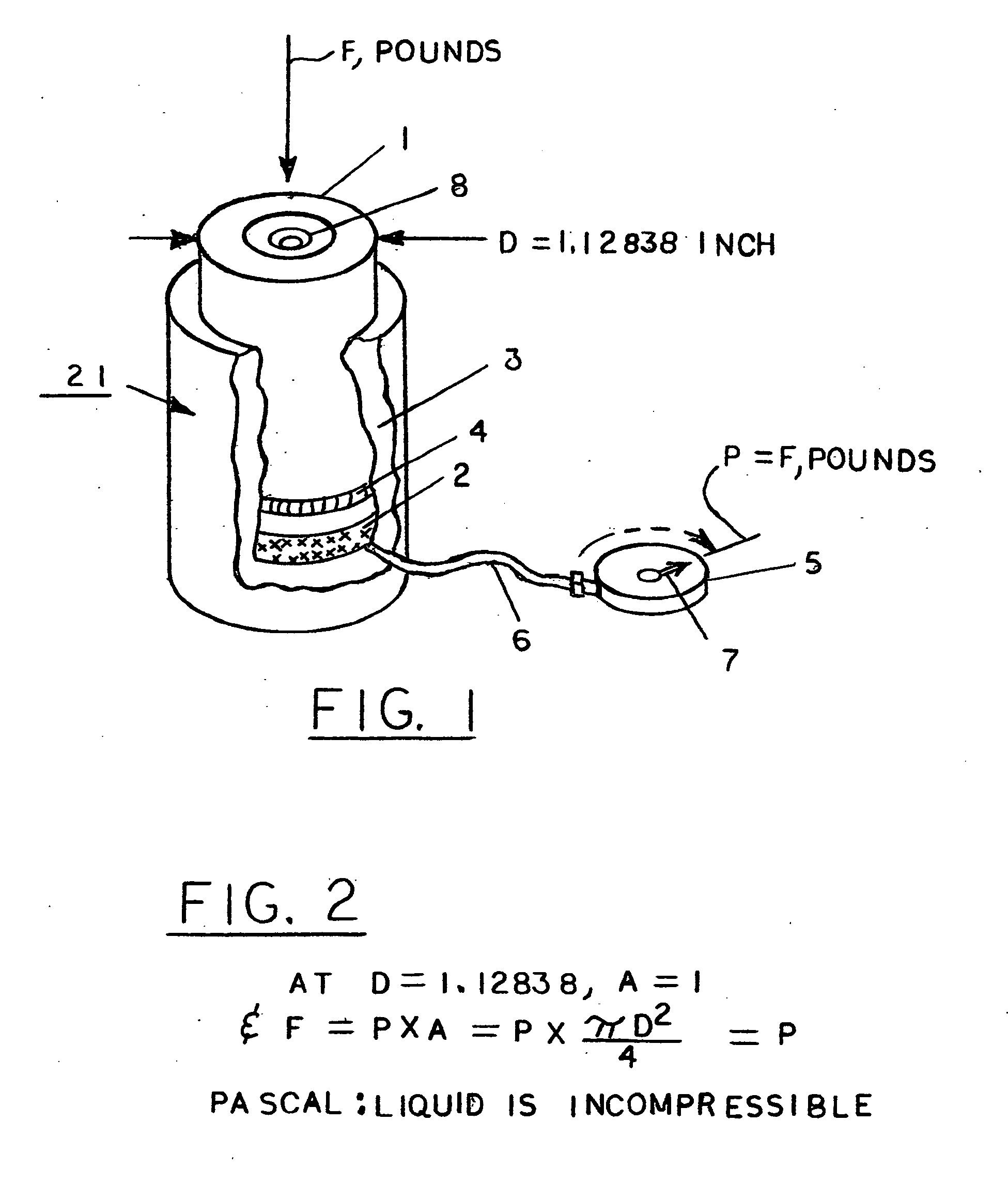
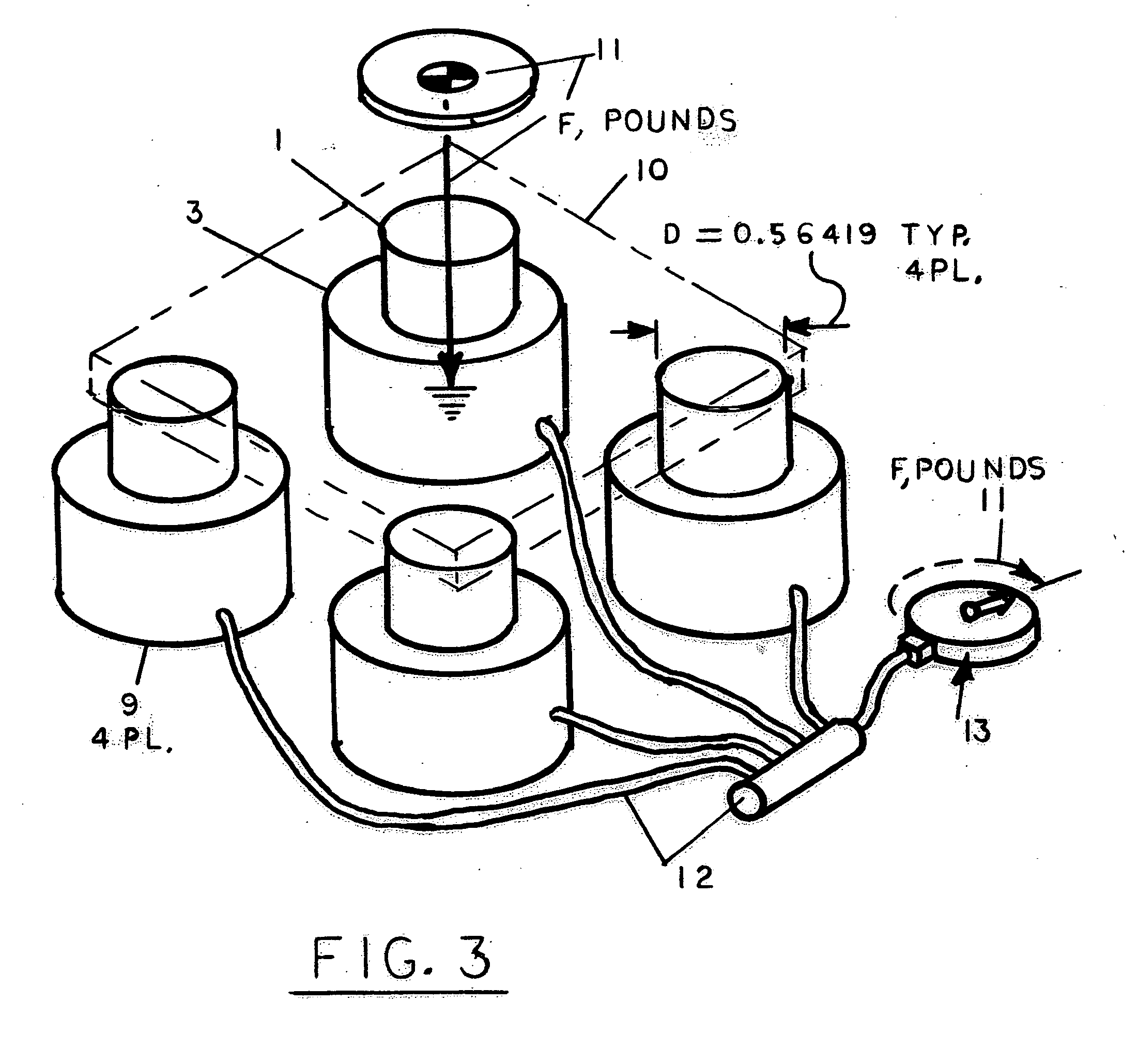
[0021]Referring to FIG. 1, a basic embodiment of the portable, hydraulic, direct force, readout apparatus 21 according to the present invention may be seen to include a piston 1 which under load F applies downward pressure to the fluid 2 contained by cylinder 3 and o'ring 4. The piston 1 is shown to have a diameter of 1.1283792±0.0001 inch which provides an area A of precisely 1 square inch.

[0022]FIG. 2 shows the mathematical relationship between pressure P, force F, and area A. Since Force F equals pressure P times area A, and area A equals π times diameter D squared divided by 4, and area is fixed at the value of one (1) because D is fixed at the value of 1.1283792 , then F is numerically=P, the key to this invention.

[0023]The assembly of the functioning elements is shown in FIG. 1. The fluid chamber 3 is connected to the gauge 5 via a small bore steel tube 6. The fluid, being incompressible, transmits the pressure numerically as “Force” directly to the gauge's needle mechanism 7,...


PUM

PropertyMeasurementUnit
diameteraaaaaaaaaa
diameteraaaaaaaaaa
surface areaaaaaaaaaaa

Abstract

A hydraulic load cell configured to allow direct readout of an applied force in pounds by a standard hydraulic gauge, which is normally calibrated in pounds per square inch. A load is applied generally to the end of the load cell's piston. The piston is fitted with an o'ring in its machined groove and inserted into a fluid filled cylinder; the cylinder having been machined to a tightly controlled diameter of nominally 1.12838 inches. The fluid cavity is joined by a small bore tube to the hydraulic gauge. The three piece device and adjoined gauge is extremely rugged. Pascal's Law of incompressibility of a liquid and the equation of Force=Pressure×Area are utilized to realize the invention's unique simplicity and usefulness. Applications to single and multiple point loading are shown.

Description

CROSS REFERENCE TO RELATED APPLICATIONS[0001]NASTATEMENT REGARDING FEDERALLY SPONSERED RESEARCH OR DEVELOPMENT[0002]NAREFERENCE TO SEQUENCE LISTINGS[0003]NABACKGROUND OF THE INVENTION[0004]A. Field of the Invention[0005]The present invention relates to the direct measurement of force applied by a load. The force may be applied in any direction, but the main usefulness illustrated in the invention is to measure vertical loads by vehicles, trailer tongue loads, product weight, and human weight as adapted to each of this situation. Generally, these applications are adapted for singular or point downward loading; the adaptation technique being left up to skill of the user. The invention provides the user with a simple rugged technique of load measurement without the usually attendant complexity of pressure-to-force conversion equipment and digital readout displays.[0006]B. Description of the Background Art[0007]Many businesses are in need of on the spot measurement of product weights an...

Claims


Application Information

Patent Timeline
Patent Type & Authority Applications(United States)
IPC IPC(8): G01L1/02
CPCG01G5/04G01L1/02G01G19/025
Inventor SHEEKS, OLIVER P.
Owner SHEEKS OLIVER P
Why Eureka
Try Eureka