Orifice sealing and reverse grouting method for in-situ leaching drill hole

A technology of grouting and orifice, which is applied in the directions of sealing/isolation, earthwork drilling and production fluid, etc. It can solve the problems of scrapped drilling, inaccurate control of the instantaneous injection amount of cement slurry, and fracture of well pipe, etc., and achieves low cost , Easy to promote on a large scale, easy to operate

Active Publication Date: 2021-11-09
中核通辽铀业有限责任公司
View PDF5 Cites 0 Cited by
  • Summary
  • Abstract
  • Description
  • Claims
  • Application Information

AI Technical Summary

Problems solved by technology

[0003] For the cementing method of forward grouting, the instantaneous injection amount of cement slurry during construction cannot be accurately controlled. If the injection amount is too large, the cement slurry will enter the casing through the bottom of the borehole, and th...

Method used


Image

  • Orifice sealing and reverse grouting method for in-situ leaching drill hole

Examples


Embodiment 1

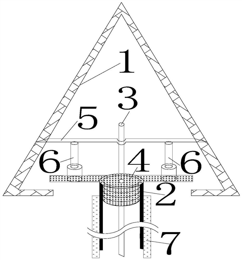
[0042](a) 1-1111 is a liquid injection drill hole in an in-situ leaching uranium mine in Inner Mongolia. The ore layer is located at 302-310 meters underground. It is drilled with a Φ215 roller cone bit and drilled to 310m. The open hole construction is completed. About 250mm; put down the well pipe (2), the well pipe (2) is a Φ100×10 UPVC pipe, connected by a screw, the depth of the screw is 2.5mm, the joint is wrapped with raw material tape and coated with 804 glue, the screw is resistant The pressure is 1.5Mpa, and the well pipe (2) is lowered to a depth of 300m in the open hole;

[0043] (b) Run the grouting pipe (3) into the well pipe (2). The grouting pipe (3) is a Φ40×3.5mm carbon steel pipe connected by a threaded thread with a depth of 1.5mm and a pressure resistance of 2.2Mpa at the joint , the grouting pipe (3) is lowered to a position of 300m, and the outlet position of the bottom end of the grouting pipe (3) is consistent with the depth of the bottom end of the we...

Embodiment 2

[0057] (a) 2-1111 is a drilling hole for pumping liquid in an in-situ leaching uranium mine in Inner Mongolia. The ore layer is located at 402 to 410 meters underground. The Φ311 roller cone bit is used to drill the open hole, and the open hole construction is completed when the hole is drilled to 410m. About 350mm; put down the well pipe (2), the well pipe (2) is a UPVC pipe of Φ152×12, connected by a threaded thread, the depth of the threaded thread is 3.0mm, the joint is wrapped with raw material tape and coated with 804 glue, the threaded thread is resistant to The pressure is 1.6Mpa, and the well pipe (2) is lowered to a depth of 400m in the open hole;

[0058] (b) Run the grouting pipe (3) into the well pipe (2). The grouting pipe (3) is a Φ40×3.5mm carbon steel pipe connected by a threaded thread with a depth of 1.5mm and a pressure resistance of 2.2Mpa at the joint , the grouting pipe (3) is lowered to a position of 400m, and the outlet position of the bottom end of th...


PUM

PropertyMeasurementUnit
The inside diameter ofaaaaaaaaaa
Wall thicknessaaaaaaaaaa
Thicknessaaaaaaaaaa

Abstract

The invention provides an orifice sealing and reverse grouting method for an in-situ leaching drill hole. According to the orifice sealing and reverse grouting method, a grouting pipe is lowered in a well pipe to the bottom of a drill hole, the earth surface orifice is sealed, a chemical pump is utilized for injecting cement paste into an annular space formed by the well pipe and an open hole from the bottom end of the well pipe through the grouting pipe, drilling mud in the annular space is replaced, according to the Pascal law principle, the drilling mud continuously returns from the earth surface, and after cement paste returns from the earth surface, it is proved that the cement paste completely replaces the drilling mud in the annular space, and reverse grouting is completed. Compared with a segmented forward grouting well cementation method, reverse grouting well cementation is more compact, and potential quality hazards existing in the grouting process are thoroughly eliminated.

Description

technical field [0001] The invention belongs to the technical field of production drilling construction technology of in-situ leaching uranium mines, and in particular relates to an in-situ leaching drilling hole opening sealing and reverse grouting process. Background technique [0002] For a long time, the cementing construction of in-situ leaching uranium mining process wells and hydrological test wells in my country has adopted the method of forward grouting. In the annular space formed by the open hole, lower the grouting pipe to the bottom of the well pipe; ③Use a chemical pump to inject the cement slurry into the bottom of the borehole through the grouting pipe; ④After injecting a certain amount of cement slurry, lift the grouting pipe to a certain distance, inject cement slurry again, lift up a certain distance again after injection, repeat the operation, and perform segmented grouting; ⑤ Lift the grouting pipe to the wellhead, complete the grouting, and the cementing ...

Claims


Application Information

Patent Timeline
IPC IPC(8): E21B33/13E21B33/03E21B43/28
CPCE21B33/13E21B33/03E21B43/28Y02P10/20
Inventor 闫纪帆李喜龙原渊张勇张万亮赵生祥阮志龙赵明曹俊鹏杨少武王丽坤董惠琦
Owner 中核通辽铀业有限责任公司
Why Eureka
Try Eureka