
Fire Tube Heater

a heater and fire tube technology, applied in the field of fire tube heaters, can solve the problems of substantial effort and expense in welding all the tubes in place within their respective tube sheets, and achieve the effect of limiting the deformation of the intermediate portion

Active Publication Date: 2011-06-23
LOCHINVAR
View PDF82 Cites 34 Cited by
  • Summary
  • Abstract
  • Description
  • Claims
  • Application Information

AI Technical Summary

Problems solved by technology

The use of relatively large numbers of relatively small diameter tubes leads to a substantial effort and expense in welding all of the tubes in place within their respective tube sheets.

Method used


Image

  • Fire Tube Heater
  • Fire Tube Heater
  • Fire Tube Heater

Examples


Embodiment Construction

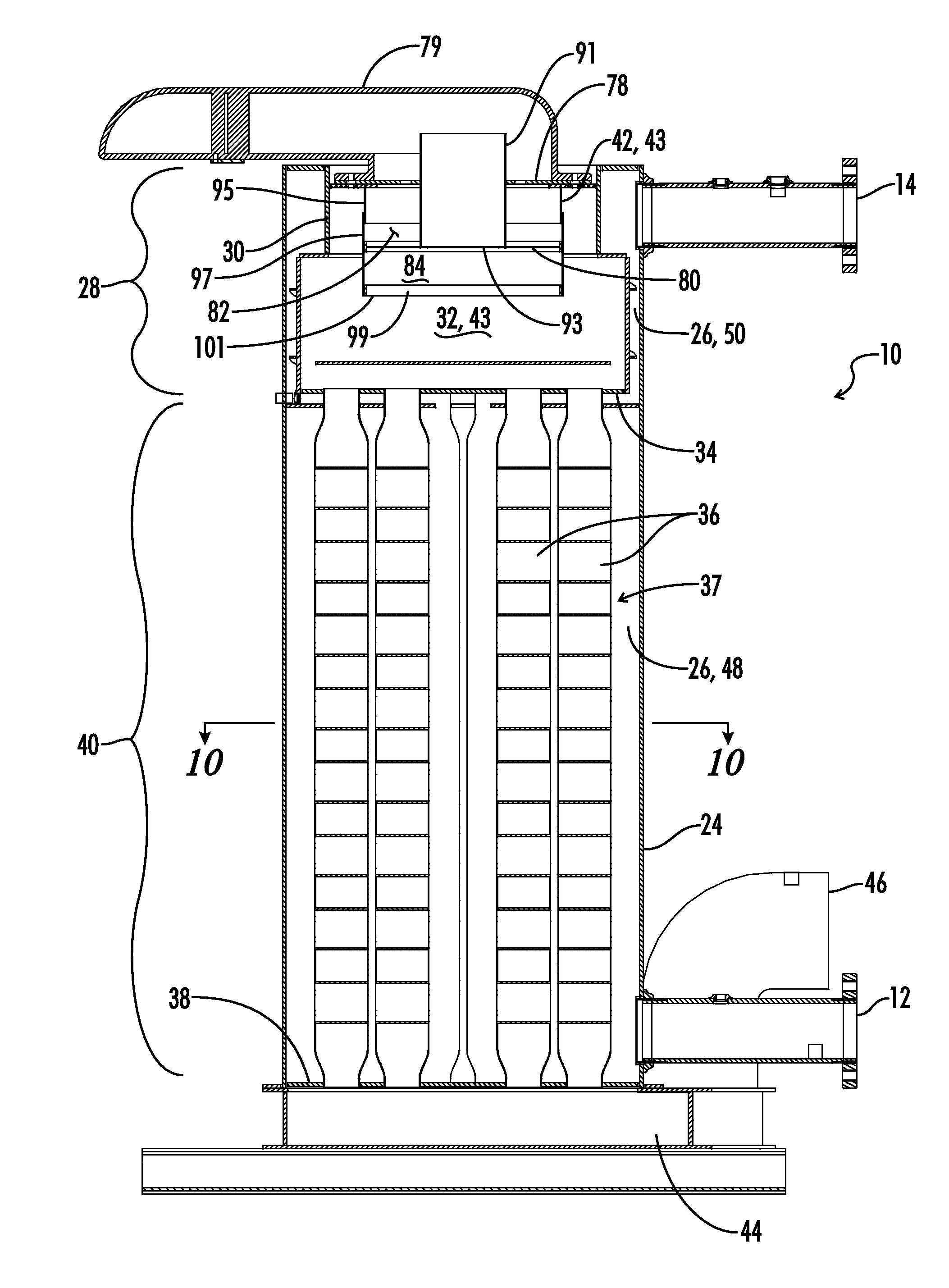
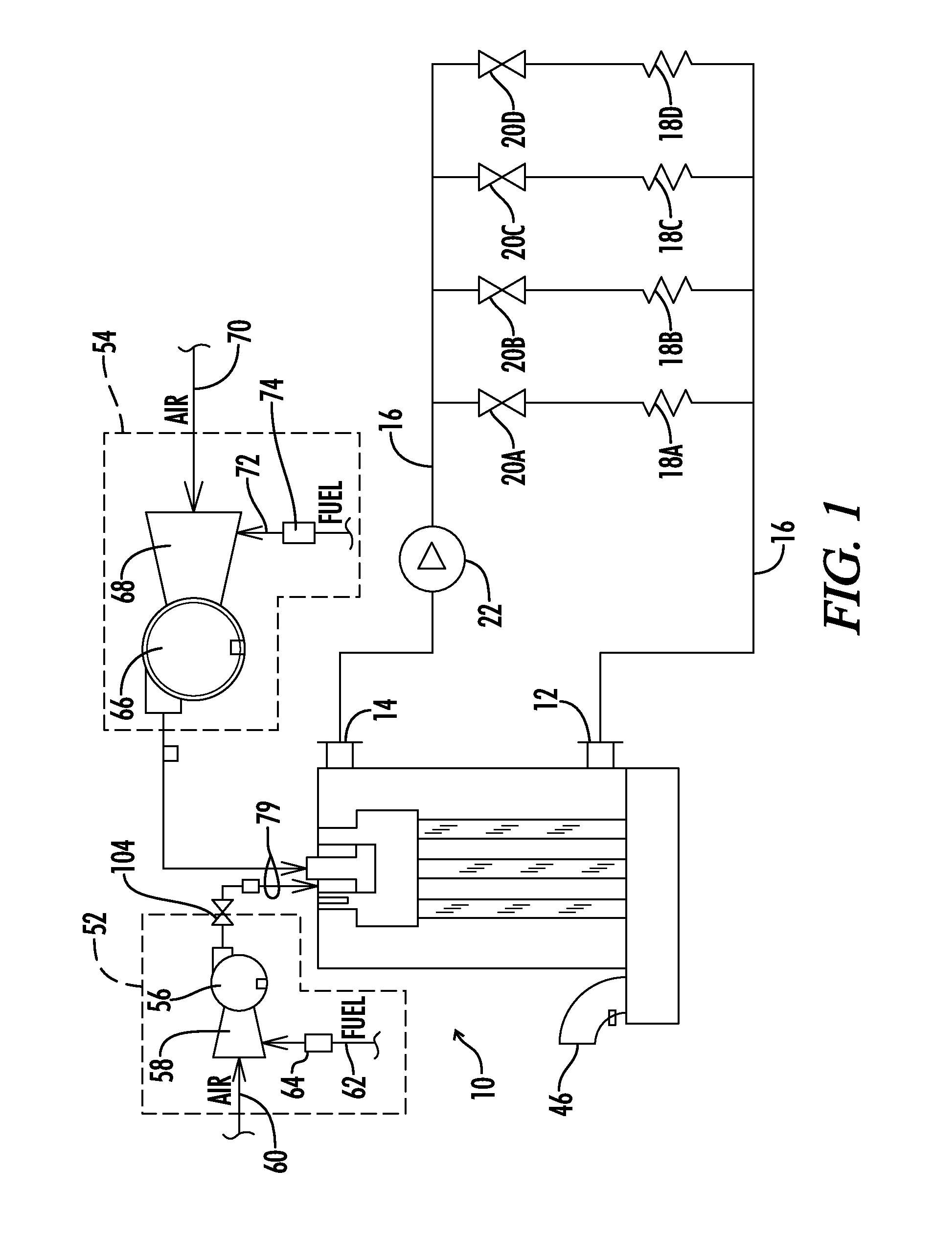
[0021]Referring now to the drawings, and particularly to FIG. 1, a water heating apparatus is shown and generally designated by the numeral 10. As used herein, the terms water heating apparatus or water heating appliance or water heater apparatus or water heater or boiler all are used interchangeably and all refer to an apparatus for heating water, including both hot water boilers and water heaters that do not actually “boil” the water. Such apparatus are used in a wide variety of commercial and residential applications including potable water systems, space heating systems, pool heaters, process water heaters, and the like. Also, the water being heated can include various additives such as antifreeze or the like.

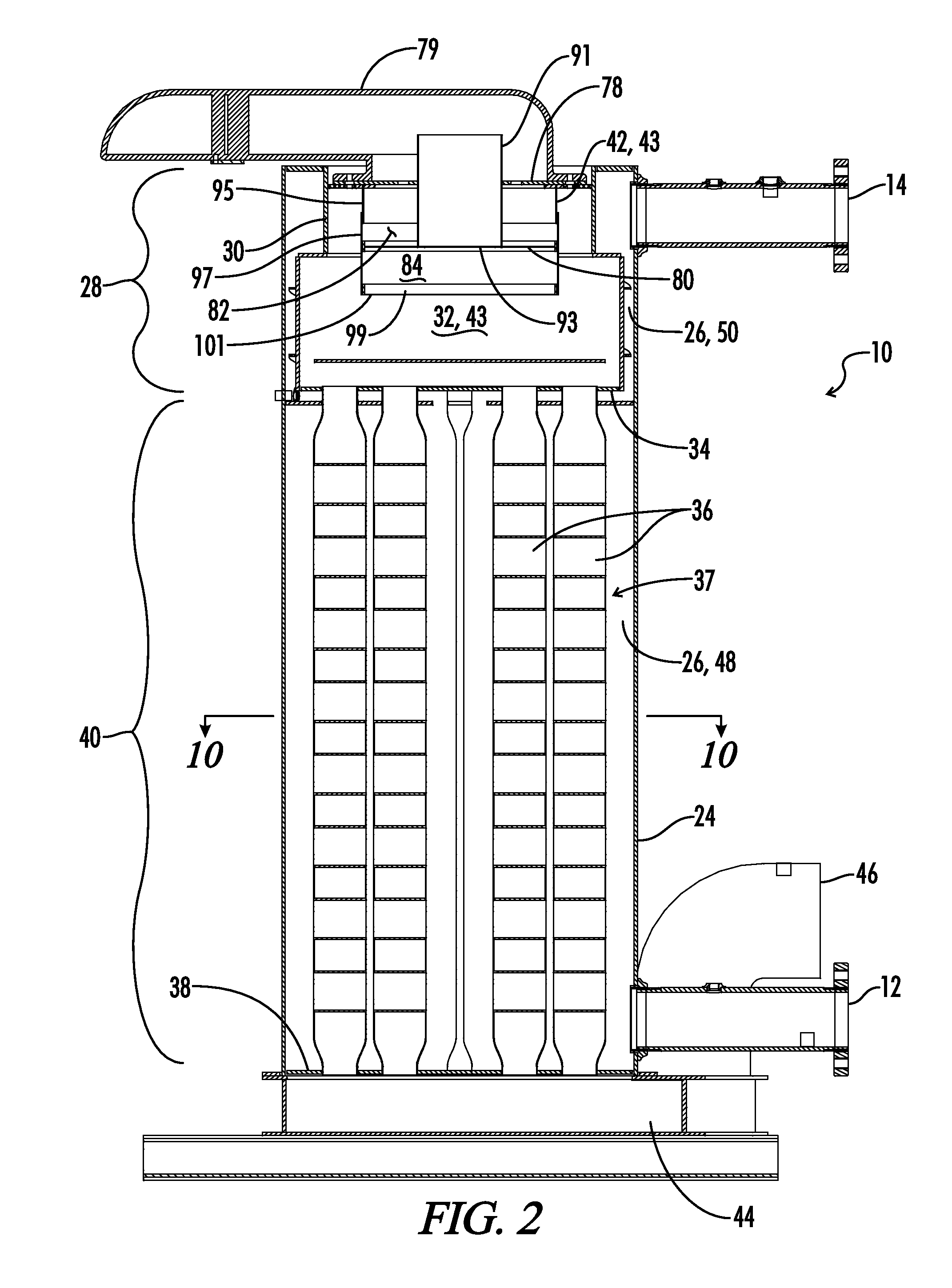
[0022]The water heating apparatus 10 illustrated in FIG. 1 is a fire tube heater. A fire tube heater is one in which the hot combustion gases from the burner flow through the interior of a plurality of tubes. Water which is to be heated flows around the exterior of the tube...


PUM


Abstract

A fire tube heater apparatus includes a shell, with a tube bundle received in the shell and a burner section communicated with the tube bundle. The tubes in the tube bundle have circular inlet and outlet end portions with a flattened, serpentine intermediate portion. The intermediate portion has a width greater than the inlet outside diameter and a tube thickness transverse to the width less than the inlet outside diameter.

Description

BACKGROUND OF THE INVENTION[0001]1. Field of the Invention[0002]The present invention relates generally to apparatus for heating water or the like, and more particularly, to the construction of heat exchange tubes of the type which carry hot combustion gases therethrough for heat exchange with water or the like flowing around the outside of the tube.[0003]2. Description of the Prior Art[0004]Traditionally heat exchangers, particularly condensing fire tube heat exchangers, have utilized a tube bundle made up of a plurality of relatively small diameter cylindrical tubes extending between an inlet tube sheet and an outlet tube sheet. Typically those tubes have been of a diameter in the range of from ½ to ¾ of an inch. This has required the use of a large number of tubes within a tube bundle to achieve the necessary heat exchange between hot combustion gases and the water or other fluid flowing around the tubes. The use of relatively large numbers of relatively small diameter tubes lead...

Claims


Application Information

Patent Timeline
Patent Type & Authority Applications(United States)
IPC IPC(8): F24H1/14F28F9/02F28F1/02F28F1/10F28D1/047
CPCF24H1/287F24H9/0026F28D7/1684F28F1/08F28F1/022F28F1/025F28F1/06F28F1/02
Inventor SMELCER, JIM C.
Owner LOCHINVAR
Learn More