

Laser Imaging and Its Use In Security Applications
- Summary
- Abstract
- Description
- Claims
- Application Information
AI Technical Summary
Problems solved by technology
Method used
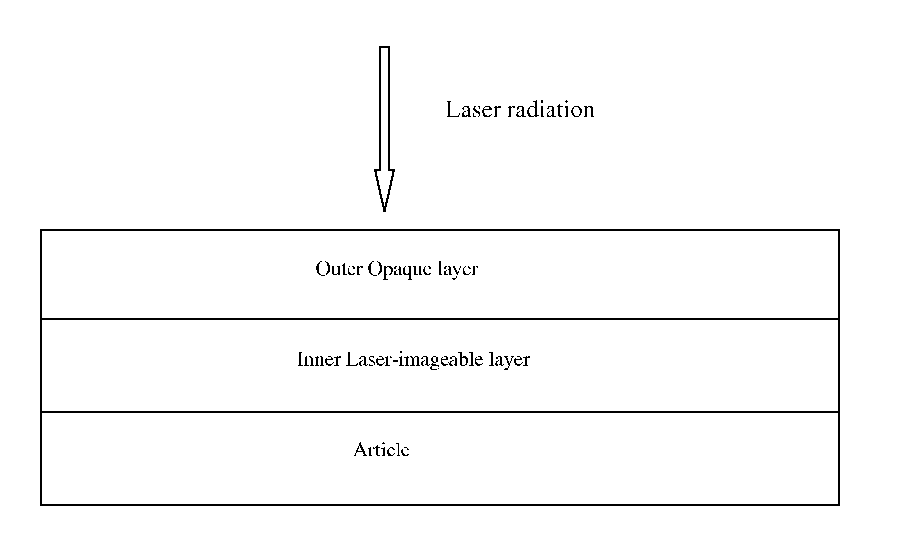
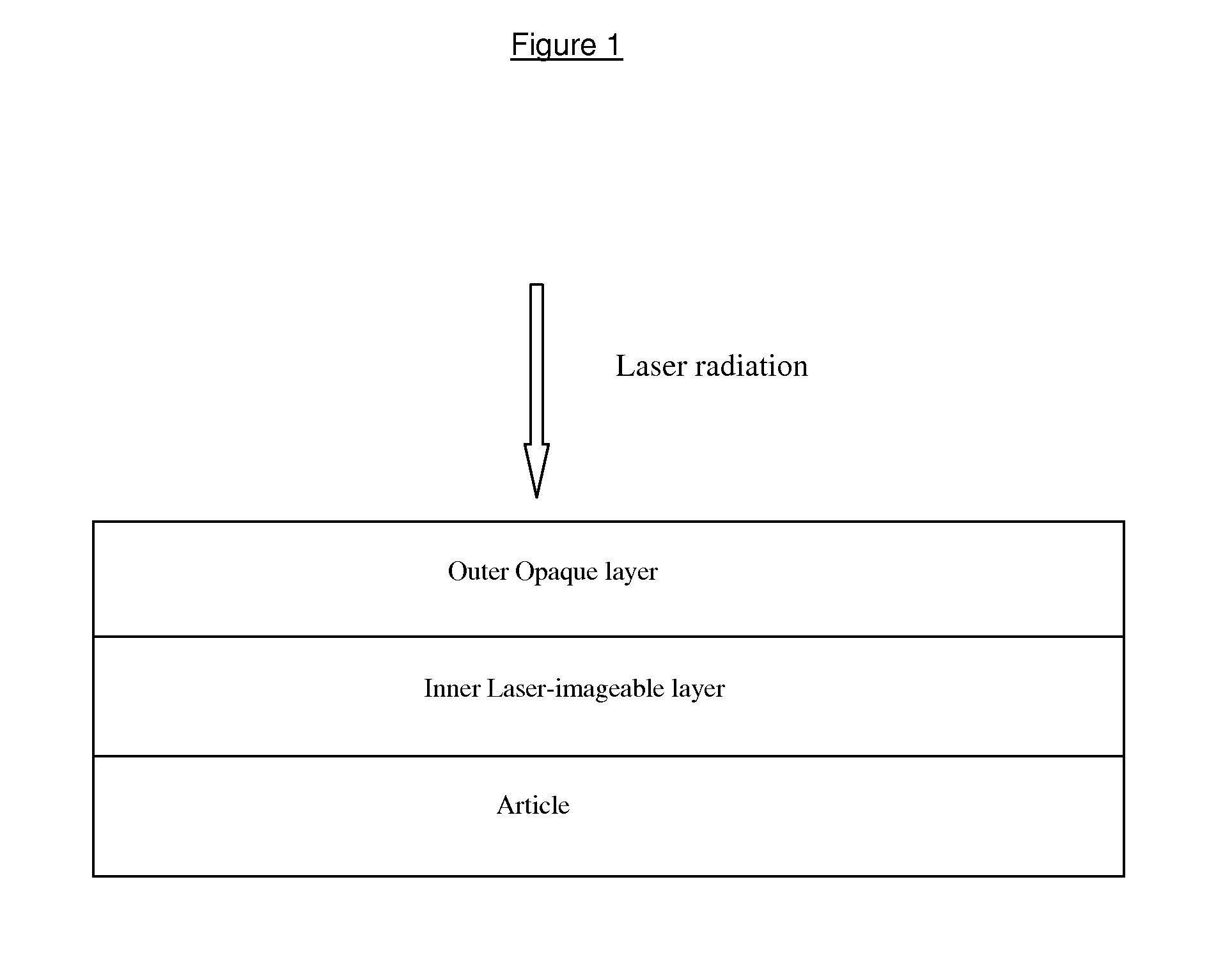
Image

Examples
example a
Outer Opaque Black Layer
[0046]The following ink formulation was prepared:
[0047]Nitrocellulose DLX3-5 dissolved in 3:1 ethanol / ethyl acetate (15%)=90 g
[0048]Paliogen Black S 0084=10 g
[0049]Mill using an Eiger-Torrance 50 ml bead mill for 15 minutes and coat on to clear PET film using a RK Proofer Printer fitted with a K-3 bar (to give about 8 gsm).
example 1
[0050]The following ink formulation was prepared:[0051]Paranol T-6320=44 g[0052]Octafoam E-235=1 g[0053]AOM=55 g
[0054]The ink was prepared using a high speed Silverson mixer for 15 minutes prior to its application to the substrate.
example 2
[0055]The following ink formulation was prepared:[0056]Paranol T-6320=44 g[0057]Octafoam E-235=1 g[0058]AOM=35 g[0059]CHP=20 g
[0060]The ink was milled using an Eiger-Torrance bead mill (50 ml) for 15 minutes prior to its application to the substrate.
PUM
| Property | Measurement | Unit |
|---|---|---|
| Wavelength | aaaaa | aaaaa |
| Wavelength | aaaaa | aaaaa |
| Wavelength | aaaaa | aaaaa |
Abstract
Description
Claims
Application Information