
Method and apparatus for filtering multicast packets

a multicast packet and filtering technology, applied in the field of multicast network technology, can solve the problems of loss of 5 bits of ip multicast address, early igmp protocol versions did not allow ssm, etc., and achieve the effect of easy detection of new frames

Inactive Publication Date: 2011-06-23
MEDIA PATENTS
View PDF99 Cites 62 Cited by
  • Summary
  • Abstract
  • Description
  • Claims
  • Application Information

AI Technical Summary

Benefits of technology

[0069]The preamble of an Ethernet frame consist of a 56-bit (7-byte) pattern of alternating 1 and 0 bits, which allows device on the network to easily detect a new incoming frame.

Problems solved by technology

Therefore, earlier IGMP protocol versions did not allow SSM.
But only half of these MAC addresses are available for use by IP multicast.
Therefore, 5 bits of the IP multicast address are lost in this process.
A problem related to multicast packet transmission occurs when a router receives a multicast packet through a network interface and it does not need to transmit the multicast packet by means of any other network interface of the router according to the router's multicast routing tables.

Method used


Image

  • Method and apparatus for filtering multicast packets
  • Method and apparatus for filtering multicast packets
  • Method and apparatus for filtering multicast packets

Examples


Embodiment Construction

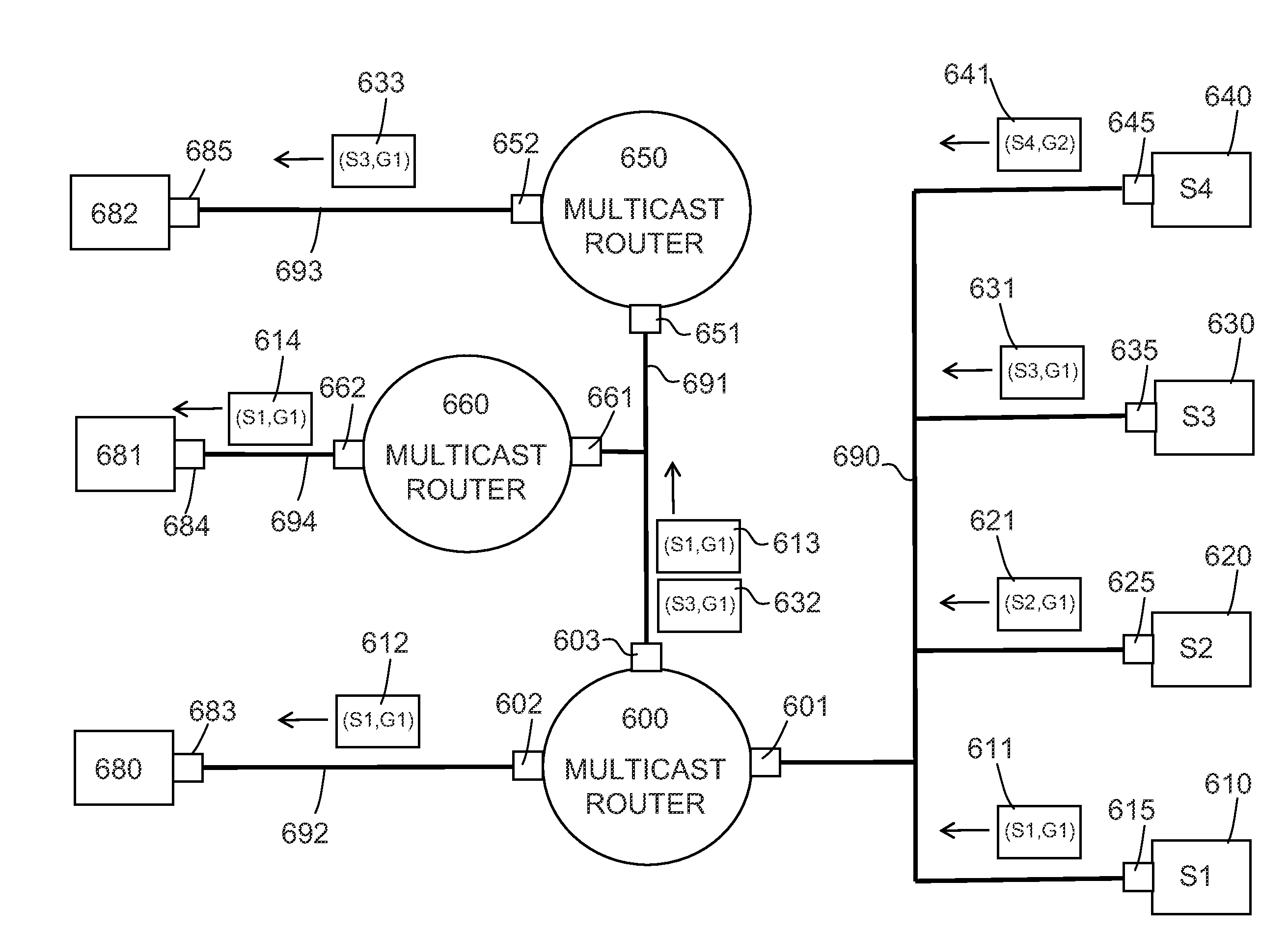
[0116]By way of illustration and for exemplary purposes only, FIGS. 7 and 8 are provided to aid in the description of the various implementations disclosed herein. It is to be understood that the computer system / router 700 of FIG. 7 and the network interface 10 of FIG. 8, as illustrated and described herein, represent several of many ways to implement the inventions disclosed herein. In addition, although the following description is based primarily on the IGMP / MLD and the PIM-SM protocols, the various implementations described herein may also be applied to other host-router protocols and other router-router protocols.

[0117]FIG. 7 is an example of a router / computing system 700 which can communicate via a network 770 with other computer systems. In one implementation router 700 includes or is otherwise connected to a network interface 760 that communicates with the router 700 via a bus 721. The router 700 includes a processor subsystem 720 which may include a processor, a memory subs...


PUM


Abstract

A method of filtering multicast packets received in a first network interface of a router is provided. The router receives multicast traffic in the first network interface from sources that send multicast packets to at least a first multicast group address. The router also having second and third network interfaces for receiving multicast traffic requests. In one implementation the filtering method includes receiving in the second network interface a first multicast traffic request for a first multicast group address according to a first multicast routing protocol including a first set of sources, receiving in the third network interface a second multicast traffic request for the first multicast group address according to a second multicast routing protocol, the multicast traffic request including a second set of sources, creating from the first and second multicast traffic requests a filter record having a third set of sources indicative of all of the sources of the first multicast group address requested to be transmitted through the second and third interfaces of the router; and filtering multicast packets received at the first network interface using the record. In alternative embodiments, multiple multicast state records (e.g., an Include source record and an Exclude source record) are stored for each network interface and multicast group address, the multiple multicast state records being used to create one or more multiple filter records that each have a set of sources that are used in combination to filter multicast packets received at the first network interface.

Description

CROSS-REFERENCE TO RELATED APPLICATIONS[0001]This application claims priority to Spanish Patent Application No. P200931198, filed Dec. 17, 2009.TECHNICAL FIELD[0002]The invention relates to the field of multicast network technology and more particularly to a method of filtering multicast packets received in a network interface of a router or similar devices.BACKGROUND[0003]Multicast technology makes it possible to send data from a single source to many recipients through a data network, without having to set up unicast communication, i.e. one-to-one individual communication between the source and each of the recipients. To that end, the source sends data, in data packet form, to a single address associated to a multicast group to which the equipment interested in being recipients of the data sending can subscribe. This address referred to as a multicast address or also as a multicast group address, is an IP (Internet Protocol) address chosen within a range that is reserved for multi...

Claims


Application Information

Patent Timeline
Patent Type & Authority Applications(United States)
IPC IPC(8): H04L12/56H04L12/28
CPCH04L12/18H04L45/16H04L12/1886
Inventor FERNANDEZ GUTIERREZ, LVARO
Owner MEDIA PATENTS
Learn More