Shear coupling assembly for use with rotary and reciprocating pumps

a technology for rotary and reciprocating pumps and shear pins, which is applied in the direction of screw, load-modified fastener, threaded fastener, etc., can solve the problems of prone to premature fatigue of shear pins, difficulty in retrieval, and difficulty in ensuring the safety of the pump, so as to improve fatigue resistance

Inactive Publication Date: 2011-06-23
WEATHERFORD TECH HLDG LLC
View PDF13 Cites 23 Cited by
  • Summary
  • Abstract
  • Description
  • Claims
  • Application Information

AI Technical Summary

Benefits of technology

A shear coupling assembly for drivably connecting between a downhole end of a rod string and a pump for use with both rotary and reciprocating pumps. The shear coupling assembly comprises a first coupling member and a second coupling member having a co-operating substantially irregular male profile and a substantially irregular female profile for mating therebetween, so as to permit transfer of torque and co-rotation during rotary pump operations. A locking member inserted into an axial bore of the first coupling member engages between the first coupling member and the second coupling member to prevent separation therebetween during rotary and reciprocating operations. A shear neck, formed on the second coupling member for permitting separation of the assembly under design loading, is positioned in an axial bore in the first coupling member when assembled and is isolated therein from corrosive fluids in the wellbore. A pretension may be applied to the shear neck to enhance fatigue resistance particularly in reciprocating pump operations or where there are deviations in the wellbore causing rotational bending in rotary pump operations. The locking member further acts to maintain the pretension, if applied.
Advantageously, in embodiments of the invention, torsional loading is applied through the mated profiles and not through the shear neck. Further, the mated profiles are located within the axial bore of the shear coupling assembly and are also protected from corrosive fluids in the wellbore, further improving fatigue resistance.

Problems solved by technology

It is known that downhole pumps may become lodged or stuck in a wellbore, often by sand deposited and packed around the pump, either at the downhole pumping location or as the pump is being tripped out of the wellbore.
Without the shear coupling, the rod string would sever at a location along the rod string that is unknown and largely unpredictable and which can be problematic for retrieval of the pump.
The shear pins are known to be prone to premature fatigue which arises from cyclic compressive stress induced in the shear pins in a reciprocating pump if the rod string “taps down” at the base of each reciprocating stroke.
Further, in either a reciprocating or rotary pump, as the shear pins break, fragments fall downhole into the pump, resulting in further problems in freeing the pump.
Shear couplings of this design are particularly suited for use in reciprocating pumps but are not useful for rotary pumps as the shear element would take virtually 100% of the torsional load.
One of skill in the art would understand that if designed for tensile loading, the addition of torsional loading as a result of rotary operation would result in premature failure.

Method used


Image

  • Shear coupling assembly for use with rotary and reciprocating pumps
  • Shear coupling assembly for use with rotary and reciprocating pumps
  • Shear coupling assembly for use with rotary and reciprocating pumps

Examples


Embodiment Construction

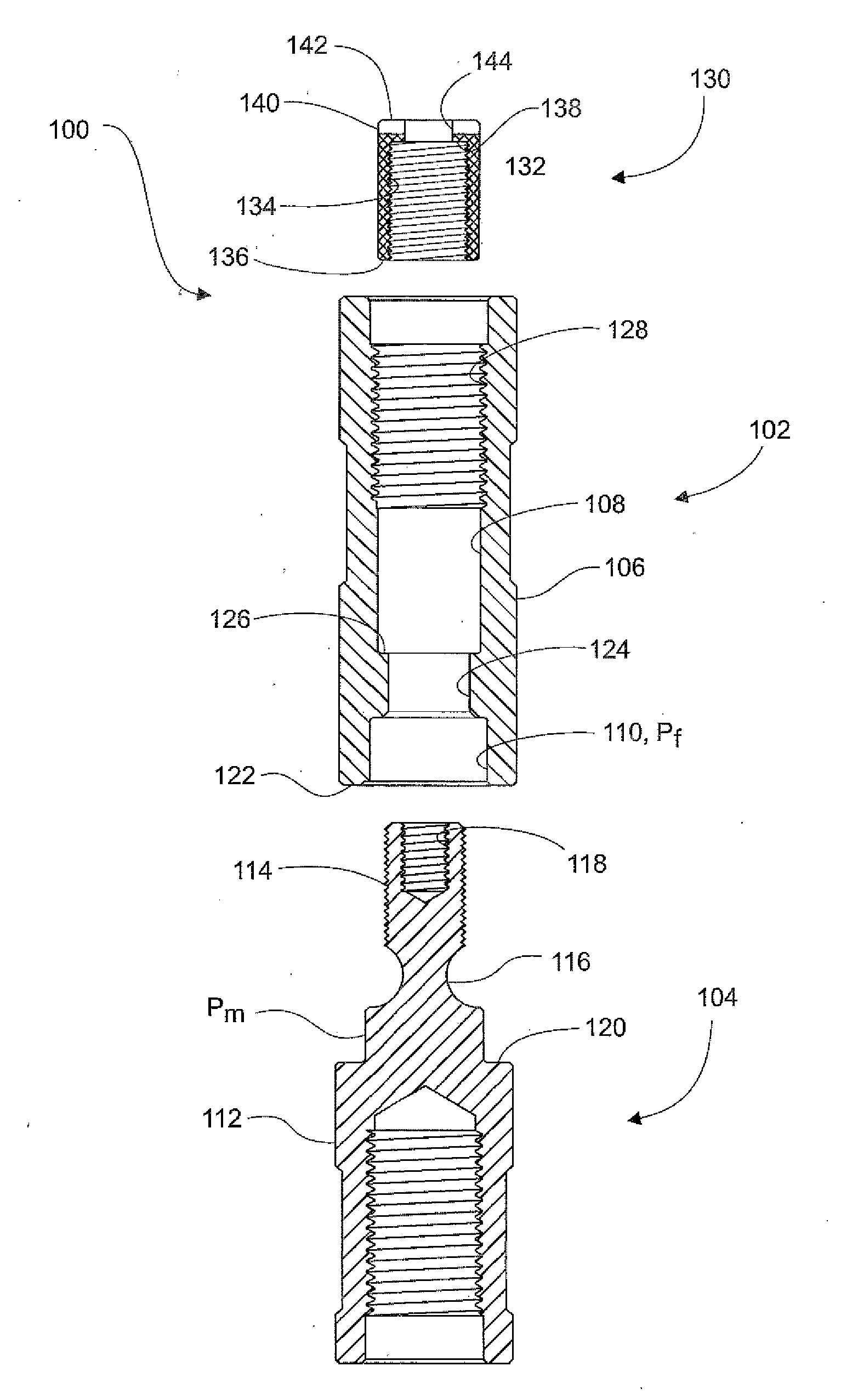
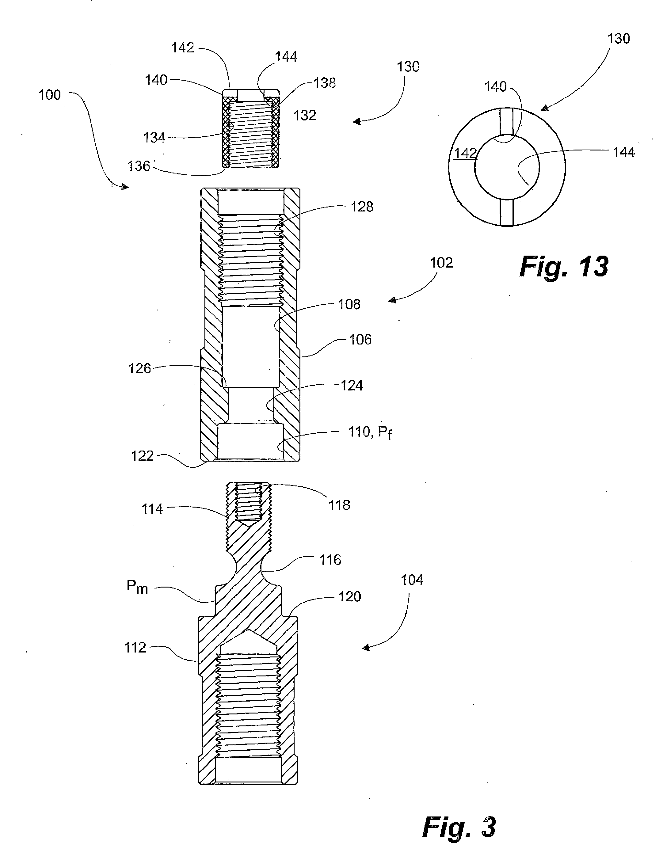
Embodiments of the invention relate to improvements to prior art shear coupling assemblies to permit use with both reciprocating and rotary pump applications. A description of a conventional shear coupling assembly and method of assembly is provided to assist in understanding embodiments of the invention and the advantages therein.

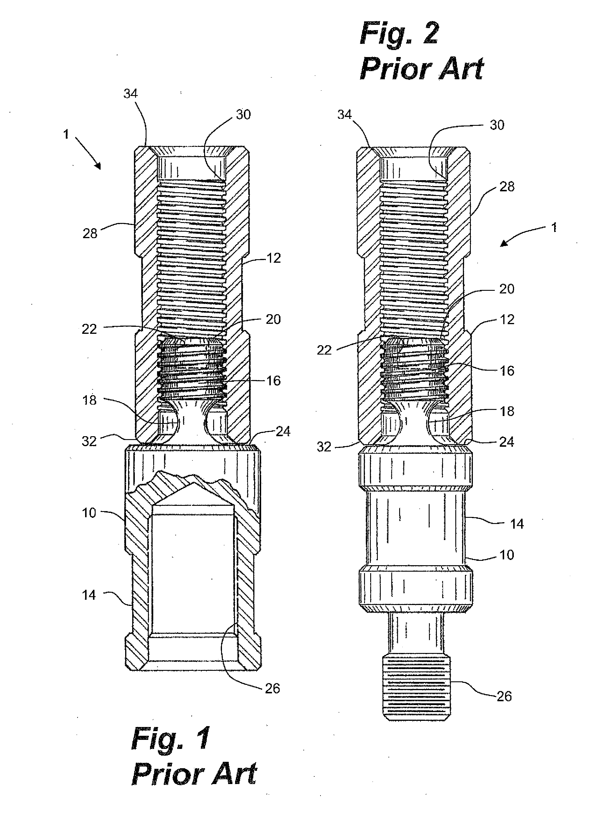
Prior Art Shear Coupling Assembly

Having reference to FIGS. 1 and 2, a conventional prior art shear coupling assembly 1, applicable to reciprocating pump applications only, comprises two members, a pin coupling member 10 and a box coupling member 12. Either of the pin or box coupling member 10, 12 can be connected to either of a pump or a rod string (not shown) for permitting connection therebetween.

The pin coupling member 10 comprises a cylindrical body 14 having an insert member 16 with external threads extending axially outwardly therefrom and connected to the body 14 by a shear neck 18 typically having a relatively reduced section. The insert member 16 ...


PUM

PropertyMeasurementUnit
pressure angleaaaaaaaaaa
areasaaaaaaaaaa
tensionaaaaaaaaaa

Abstract

A shear coupling assembly utilizes a second coupling member, a first coupling member and a locking member which is inserted into a bore in the first coupling member to connect between the second coupling member and the first coupling member. In embodiments where a pretension is applied to the shear neck, the locking member maintains the pretension in the shear neck. The bore of the first coupling member has a profiled section which corresponds to a profiled section on the second coupling member which when mated together permit torque to be transferred for co-rotating the second coupling member with the first coupling member for use in rotary pump operations. Advantageously, the profiled portions and the shear neck are encased in the bore of the shear coupling assembly and are protected from corrosive wellbore fluids.

Description

CROSS REFERENCE TO RELATED APPLICATIONThe present application claims priority to Canadian Application 2,688,801 filed on 17 Dec. 2009, the contents of which are incorporated herein by reference.FIELD OF THE INVENTIONEmbodiments of the invention relate to a shear coupling assembly used for connecting a downhole pump to a terminal end of an actuating rod string in pumped wells, and more particularly to a shear coupling for use with rotationally driven rod pumps.BACKGROUND OF THE INVENTIONDownhole reciprocating and rotary pumps are positioned and actuated in a wellbore by a rod string extending from surface. The rod string is typically either one continuous member or a plurality of sucker rods, connected end-to-end through standard threaded couplings.It is known that downhole pumps may become lodged or stuck in a wellbore, often by sand deposited and packed around the pump, either at the downhole pumping location or as the pump is being tripped out of the wellbore. Conventionally, the ...

Claims


Application Information

Patent Timeline
Patent Type & Authority Applications(United States)
IPC IPC(8): F16B31/00B23P11/00
CPCE21B17/06F16B31/021Y10T29/49963F16D9/08Y10T29/49966F16B37/12
Inventor WOLODKO, BENNY B.BASLER, HERMANNPENNER, JONATHAN PAUL
Owner WEATHERFORD TECH HLDG LLC
Why Eureka
Try Eureka