Intraocular lens injector including a shaped spring

a technology of injector and injector, which is applied in the field of intraocular lens injector, can solve the problems of unfavorable stability and tilting, and the plunger may be particularly unstable, and achieve the effects of reducing the tilting of the plunger, improving the stability of the injector lumen, and improving centrifugal for

Inactive Publication Date: 2011-06-23
BAUSCH & LOMB INC
View PDF29 Cites 9 Cited by
  • Summary
  • Abstract
  • Description
  • Claims
  • Application Information

AI Technical Summary

Benefits of technology

[0010]Aspects of the present invention are directed to improving centration and / or reducing tilting of the plunger. According to aspects of the invention, an injector is provided with a plunger spring having coils of different outer diameters to contact a lumen wall and thereby provide improved stability within an injector lumen.

Problems solved by technology

Typically, a plunger shaft is supported by an inner surface 36 of the lumen using one or more contact points (e.g., where the plunger rests due to gravity) resulting in undesirable instability and tilting (i.e., decentration) of the plunger within the lumen.
A plunger may be particularly unstable at points of the stroke near full retraction, where interface I between the plunger and the injector body is relatively short.
Plunger stability and centration with respect to the lumen may be particularly troublesome for molded plastic injectors, but also occurs in other injectors.

Method used


Image

  • Intraocular lens injector including a shaped spring
  • Intraocular lens injector including a shaped spring
  • Intraocular lens injector including a shaped spring

Examples


Embodiment Construction

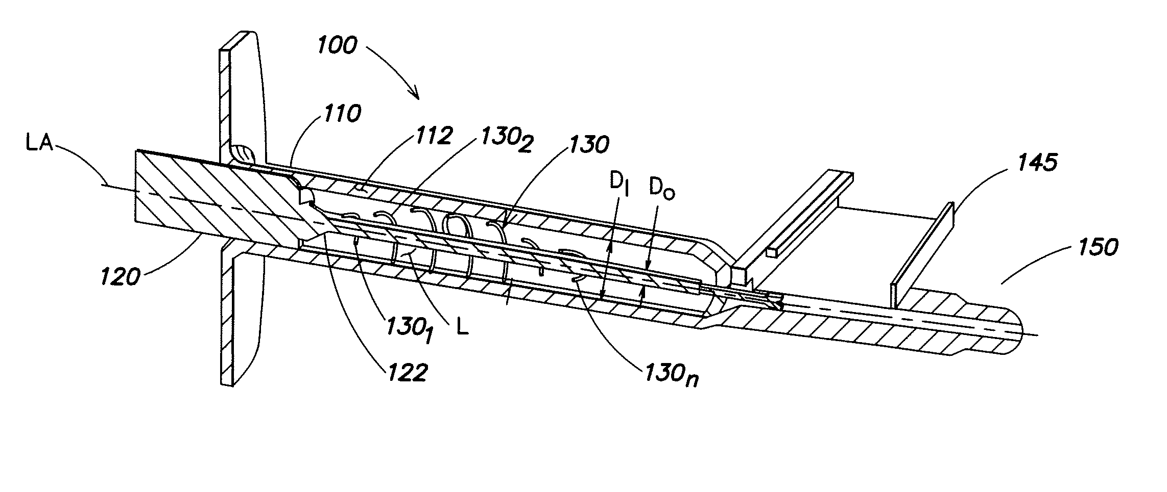
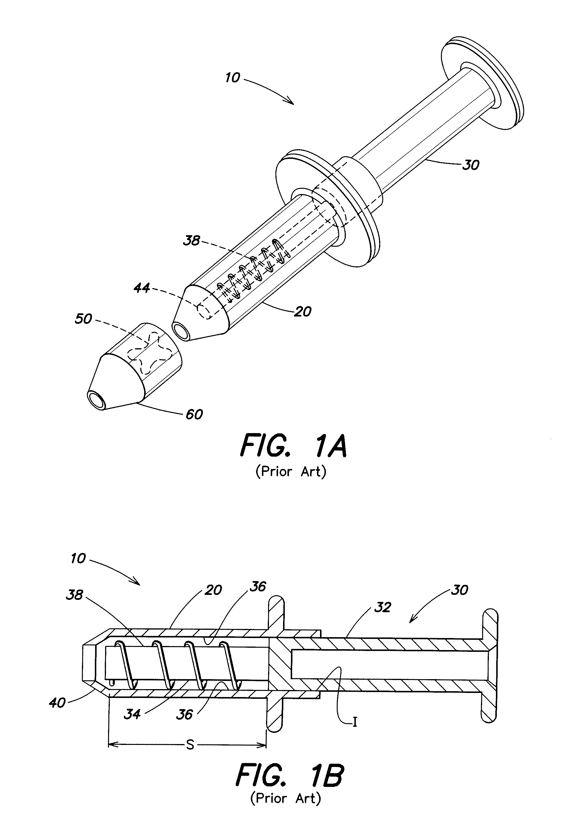
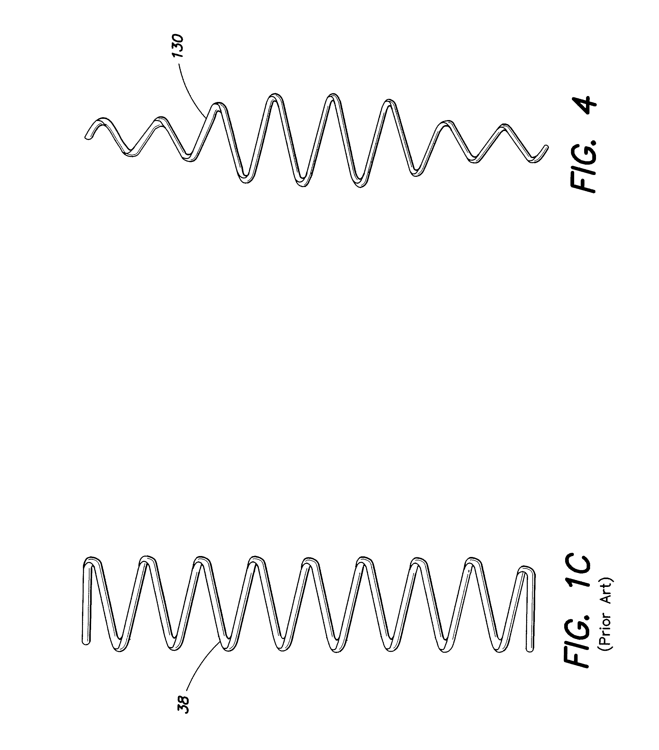
[0025]FIG. 2 is a cutaway, schematic illustration of an example of an IOL injector 100 according to aspects of the present invention. Injector 100 comprises an injector body 110 and a plunger 120 having a plunger spring 130 coupled thereto. It will be appreciated that an injector according to aspects of the present invention may be configured substantially similarly to any suitable prior art injector except the plunger spring is suitably shaped.

[0026]The injector body has a lumen L defined by a lumen wall 112. The lumen may have any suitable cross-sectional shape which may change along the longitudinal axis of the injector. For example, a lumen may have a round, oval, triangular, quadrilateral or elliptical shape or other suitable shape, and may change shapes along the longitudinal axis LA.

[0027]Plunger 120 is adapted to slide within lumen L. The plunger is coupled to spring 130. The plunger has a plurality of coils 1301-130n of different outer diameters (i.e., at least two coils of...


PUM


Abstract

An intraocular lens (IOL) injector comprising an injector body having a lumen defined by a lumen wall, and a plunger adapted to slide within the lumen. The plunger is coupled to a spring having a plurality of coils, the plurality comprising at least one coil of a first outer diameter and at least one coil of second outer diameter that is different than the first outer diameter.

Description

FIELD OF INVENTION[0001]The present invention relates to intraocular lens (IOL) injectors, and more particularly to IOL injectors providing plunger control using a shaped spring.BACKGROUND OF THE INVENTION[0002]IOLs are artificial lenses used to replace or supplement the natural crystalline lenses of patients' when their natural lenses are diseased or otherwise impaired. IOLs may be placed in either the posterior chamber or the anterior chamber of an eye. IOLs come in a variety of configurations and materials.[0003]Various instruments and methods for implanting such IOLs in an eye are known. Typically, an incision is made in a patient's cornea and an IOL is inserted into the eye through the incision. In one technique, a surgeon uses surgical forceps to grasp the IOL and insert it through the incision into the eye. While this technique is still practiced today, more and more surgeons are using IOL injectors, which offer advantages such as affording a surgeon more control when inserti...

Claims


Application Information

Patent Timeline
Patent Type & Authority Applications(United States)
IPC IPC(8): A61F9/007
CPCA61F2/1664
Inventor SEYBOTH, WILLIAM J.CULLEN, JON P.BIDDLE, GRAHAM W.ENGIN, EMIN
Owner BAUSCH & LOMB INC
Why Eureka
Try Eureka