
Driver-based control system and method to improve fuel economy

a control system and driver technology, applied in the direction of electrical control, process and machine control, etc., can solve the problems of not providing any means of active compensation, unable to consider that some drivers will not actively respond, and difficulty in adapting, so as to improve fuel economy and mitigate the negative effects of aggressive driving styles

Active Publication Date: 2011-06-23
FCA US
View PDF25 Cites 30 Cited by
  • Summary
  • Abstract
  • Description
  • Claims
  • Application Information

AI Technical Summary

Benefits of technology

[0005]In various example embodiments, the technology described herein achieves fuel economy optimization through active compensation of driver controlled input(s). The technology also provides indexing and characterization of real time driving measurables, including generating driver feedback. The active compensation functionality is used to moderate ‘sweet spot’ vehicle response with driver desired performance. In particular, the active compensation functionality can be used to smooth the vehicle response and attenuate undesired frequency content from the driver input. One of the benefits to this system and method is that they assist all drivers in achieving better fuel economy for real world driving. Another benefit is that active compensation of driver controlled inputs can mitigate some of the negative effects of more aggressive driving styles.

Problems solved by technology

These types of systems, however, suffer from a number of fallbacks, mainly that they do not provide any means for active compensation.
These systems fail to consider that some drivers will not actively respond to coaching; others may have difficulty adapting because of slow reaction times or inexperience.
Further, current techniques do not provide any real-time indexing, characterization, or feedback on the driver's actions or the vehicle's status.

Method used


Image

  • Driver-based control system and method to improve fuel economy
  • Driver-based control system and method to improve fuel economy
  • Driver-based control system and method to improve fuel economy

Examples


Embodiment Construction

[0017]Before describing the disclosed embodiments of the technology in detail, it is to be understood that the technology is not limited in its application to the details of the particular arrangement shown here since the technology is capable of other embodiments. Also, the terminology used herein is for the purpose of description and not of limitation.

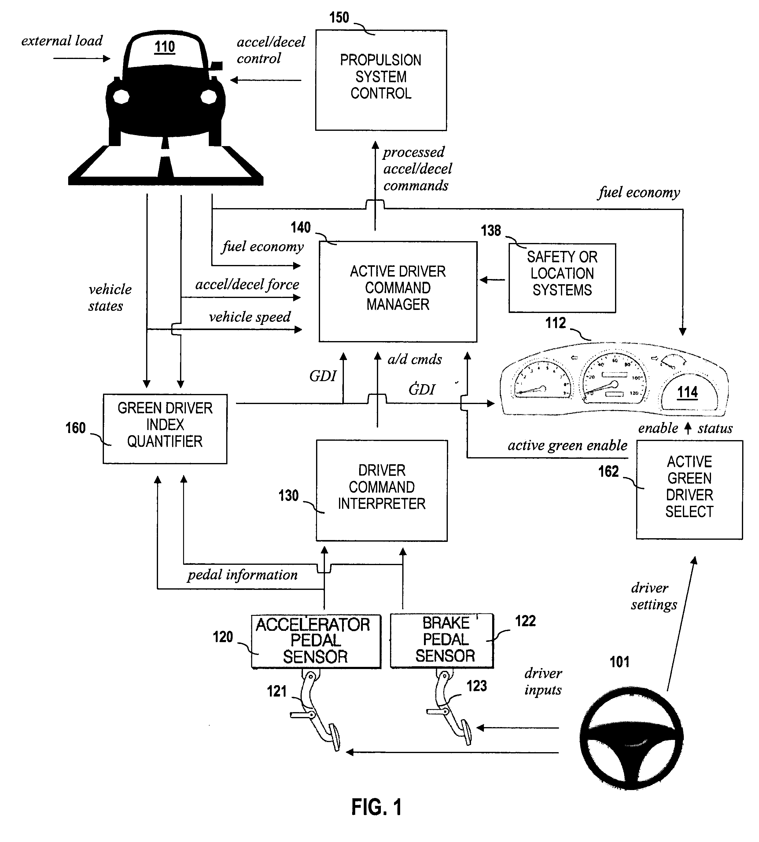
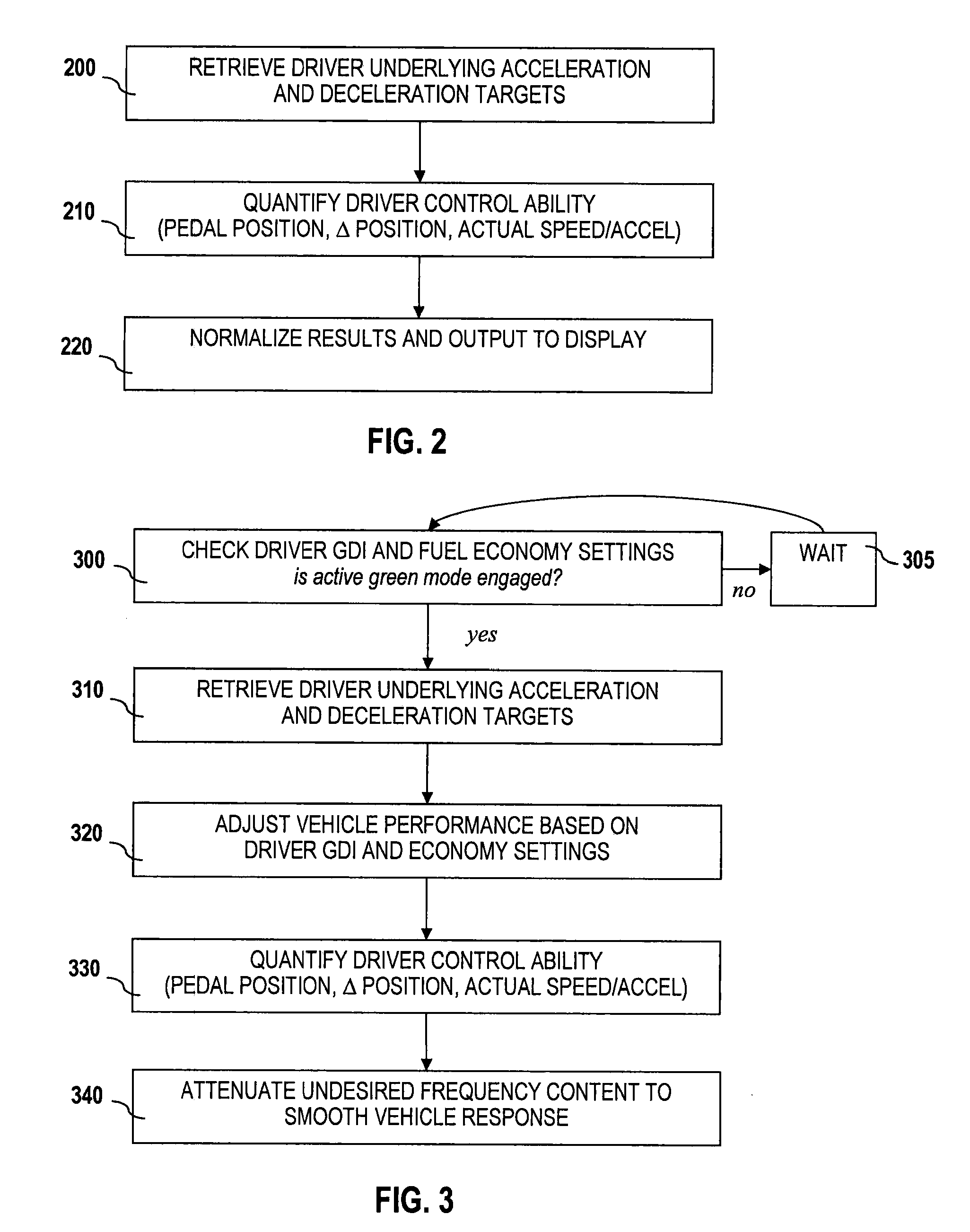
[0018]In various example embodiments, the technology described herein increases vehicle fuel economy by monitoring driver controlled inputs and actively attenuating vehicle response based on pedal position, rate of change of pedal position, and actual vehicle speed and acceleration. The active compensation functionality is used to correlate ‘sweet spot’ vehicle response with driver desired performance.

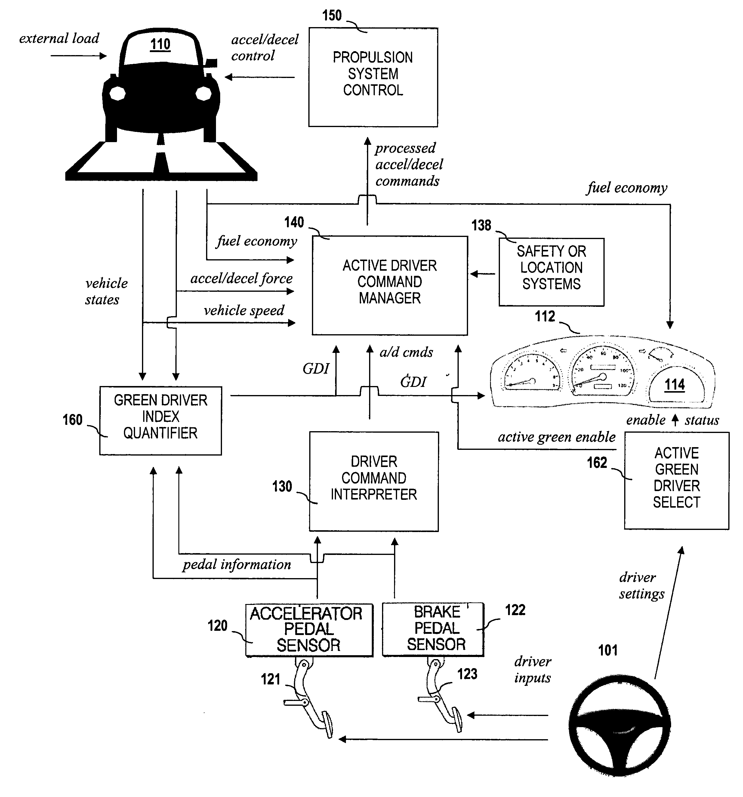
[0019]Referring now to FIG. 1, which shows an active driver control system 100, driver 101 operates vehicle 110 by actuating the accelerator control pedal 121 and brake control pedal 123. Pedal actuation is detected by accelerator pedal...


PUM


Abstract

The technology described herein provides an active driver control system. Additionally, in various example embodiments, this technology provides methods for optimizing fuel economy (or energy consumption) through active compensation of driver controlled inputs. The active compensation functionality is used to moderate ‘sweet spot’ vehicle response with driver desired performance. In particular, the active compensation functionality can be used to smooth the vehicle response and attenuate undesired frequency content from the driver input. One of the benefits to this technology is that it assists all drivers in achieving better fuel economy in real world driving. Another benefit is that active compensation of driver controlled inputs can mitigate some of the negative effects of more aggressive driving styles. In addition to active compensation functionality, the technology described herein is also capable of generating a Green Driver Index which is derived by quantifying the driver's control ability and normalizing the result against desired fuel economy and performance targets.

Description

FIELD OF THE INVENTION[0001]The technology herein relates generally to improving fuel economy of a motor vehicle and more particularly to using vehicle and driver measurables to index, in real time, driver control ability and actively compensate driver input to achieve better fuel economy in real world driving.BACKGROUND OF THE INVENTION[0002]Real world vehicle fuel economy innately depends on driver ability and performance preference. Fuel economy is, in fact, affected substantially by how the vehicle is operated; in many cases, how the vehicle is operated can affect fuel economy more than technological improvements. Driver behaviors that contribute to decreased fuel economy include high acceleration and constant starts and stops, which consume fuel without saving time. Idling is another culprit of decreased fuel economy.[0003]Generally, it is understood that to achieve ideal fuel economy, drivers must consistently maintain smooth acceleration and deceleration and strive to operate...

Claims


Application Information

Patent Timeline
IPC IPC(8): F02D41/00F02D43/00G06F19/00
CPCB60K2350/1092B60T2220/02B60W40/09B60W2540/12B60W2520/10B60W2520/105B60W2540/10B60W50/14Y02T10/84B60K35/28B60K2360/172B60K2360/174
Inventor ZHANG, MENGYANGIYENGAR, JAYANTHI
Owner FCA US
Learn More