Instrument apparatus

a technology for instruments and display devices, applied in instruments, fluid pressure measurement, transportation and packaging, etc., can solve the problems of hindering the miniaturization of instruments, and achieve the effect of improving the operability of mounting, facilitating the operation of mounting the second display device, and smooth fitting

Active Publication Date: 2011-06-30
YAZAKI CORP
View PDF0 Cites 17 Cited by
  • Summary
  • Abstract
  • Description
  • Claims
  • Application Information

AI Technical Summary

Benefits of technology

[0014]According to the present invention, as mentioned above, by inserting the projecting portion of the second display device through the insertion hole of the chaptering plate, the second display device and the circuit body can be electrically connected with the connecting terminal and the terminal receiving member. Thereby, operation of mounting the second display device can be simplified. No operation space for electrically connecting the second display device and the circuit board by an operator is required, so that the instrument apparatus can be miniaturized.
[0015]According to the present invention, by inserting the projecting portion through the insertion hole, the connecting terminal and the terminal receiving member can be positioned corresponding to each other by the boss and the positioning hole. Thereby, the connecting terminal and the terminal receiving member can be smoothly fitted and operability of mounting can be improved. The connecting terminal and the terminal receiving member can be securely fitted to each other and fitting error of the connecting terminal and the terminal receiving member can be prevented.

Problems solved by technology

Additionally, larger working area for connecting by a worker is required so that miniaturizing the instrumental apparatus is hindered.

Method used


Image

  • Instrument apparatus
  • Instrument apparatus
  • Instrument apparatus

Examples


Embodiment Construction

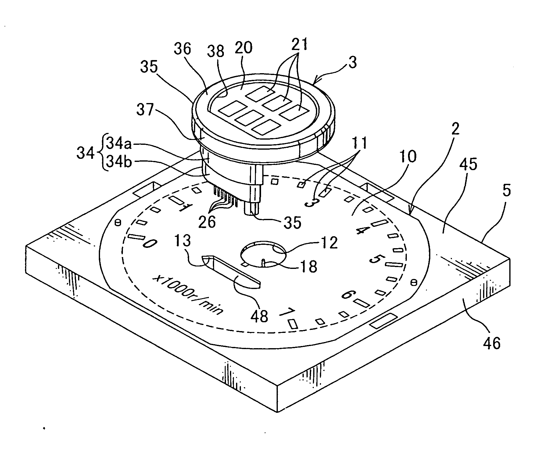
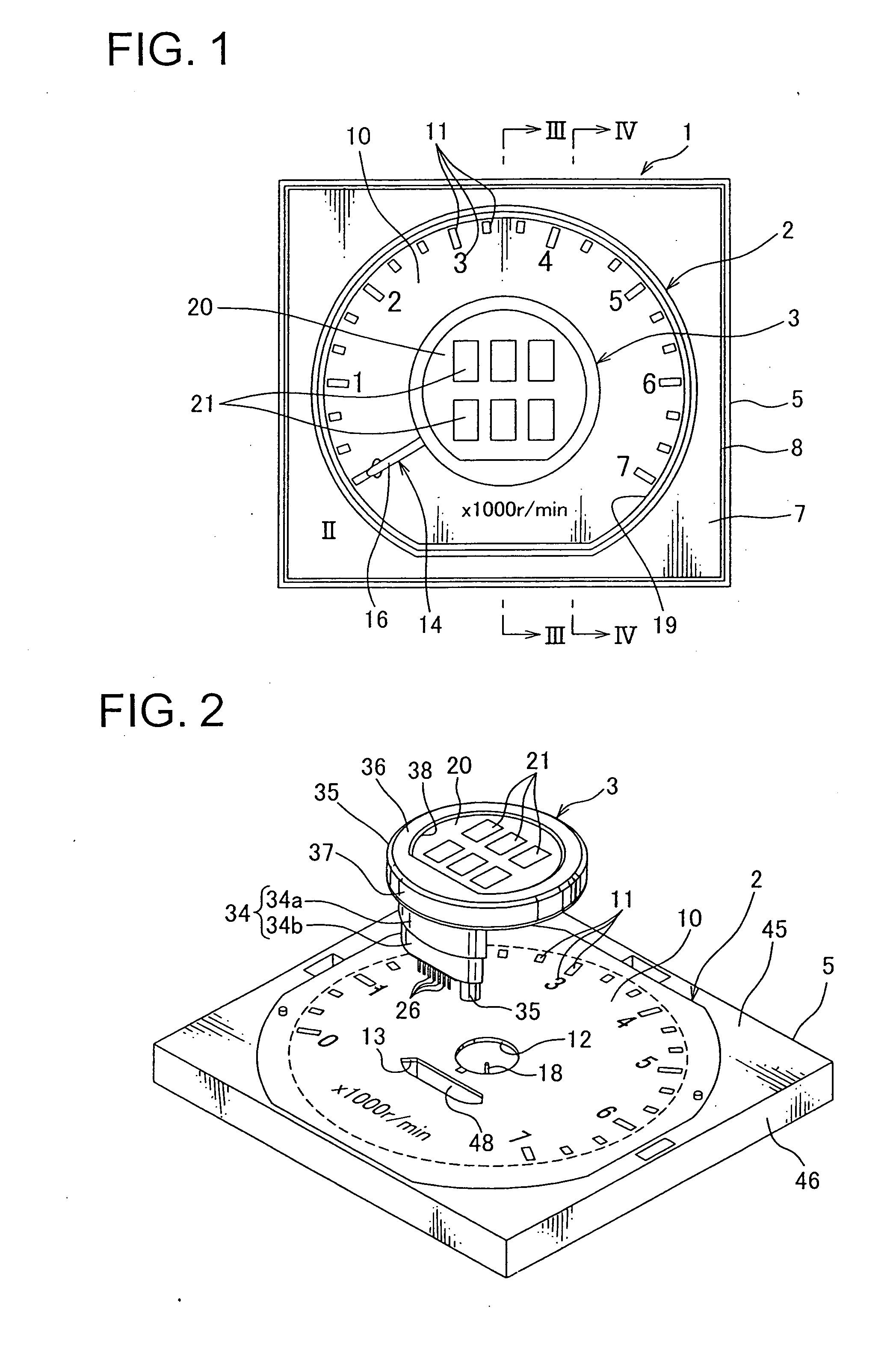
[0022]An instrument apparatus of a first embodiment according to the present invention is described with reference to FIGS. 1-5. The instrument apparatus 1 of the first embodiment according to the present invention is mounted at a movable body such as an automobile for displaying a condition of the movable body toward a crew of the movable body.

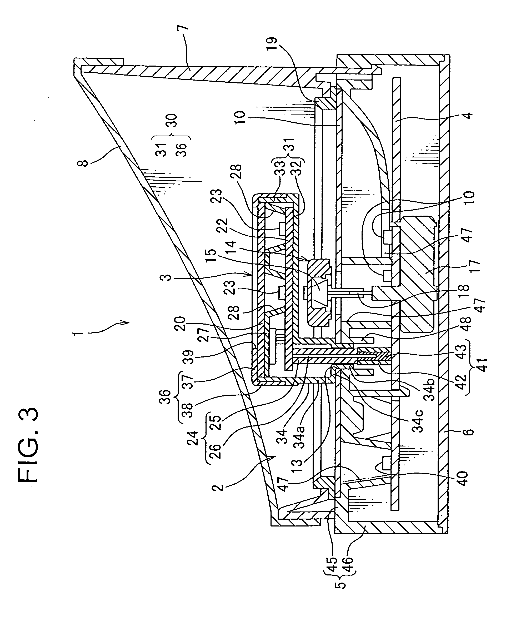
[0023]The instrument apparatus 1, as shown in FIG. 1, includes a tachometer 2 as the first display device for showing a revolution speed of an engine of the movable body; a display unit 3 as the second display device for showing various information; a printed circuit board 4, on which various electronic components are mounted, as a circuit board; an instrument case 5 receiving the tachometer 2, the display unit 3 and the printed circuit board 4; a rear cover 6 covering a rear surface of the instrument case 5, which the rear surface is a side farther from a crew of the movable body; an inside member 7 arranged at a crew side, i.e. a side of a ...


PUM


Abstract

An instrument apparatus, includes a tachometer having a chaptering plate provided at a front surface thereof; a display unit arranged at the front surface of the chaptering plate; a printed circuit board arranged at a rear surface of the chaptering plate and driving the display unit. The display unit includes a projecting portion projecting toward the chaptering plate and a male terminal provided at a top end of the projecting portion. The chaptering plate includes an insertion hole formed into a similar shape as an outline of the projecting portion, in which the projecting portion is inserted. The printed circuit board is arranged at a position, in which an insert direction of inserting the projecting portion through the insertion hole and the printed circuit board intersect, and includes a female terminal to be fitted and electrically connected with the male terminal.

Description

TECHNICAL FIELD[0001]This invention relates to an instrument apparatus mounted at a movable body such as a vehicle or shipping, especially to an instrument apparatus having a display device showing predetermined information.BACKGROUND ART[0002]In the movable body such as the vehicle or shipping, an instrument apparatus showing information measured by various measuring devices for a crew of the movable body. An analogue instrument apparatus, which, for example, rotates an indicating needle in accordance with a measuring value measured by the various measuring devices so as to point an index member showing various condition of the movable body at a chaptering plate by the indicating needle, so that the measuring value is shown for the crew of the movable body, is used as the instrumental apparatus.[0003]The analogue instrumental apparatus includes a box-shaped instrument case; a chaptering plate mounted at a crew side of the instrument case, and having an index member showing various ...

Claims


Application Information

Patent Timeline
Patent Type & Authority Applications(United States)
IPC IPC(8): G01D11/24
CPCB60K37/02B60K2350/1064B60K2350/302G01D7/00B60K2350/402B60K2350/945B60K2350/948B60K2350/307B60K2370/154B60K2370/42B60K2370/46B60K2370/695B60K2370/828B60K2370/834B60K2370/336G01D2207/30
Inventor ISHIHARA, HIDEO
Owner YAZAKI CORP
Why Eureka
Try Eureka