

Vehicle electrical conduction path
a technology of electrical conduction path and vehicle, which is applied in the direction of cable termination, transportation and packaging, organic chemistry, etc., can solve the problems of inconvenient connection of parts to devices, power cables and control cables cannot be held in a desired wiring shape, and the time-consuming and costly painting process, etc., to achieve convenient branching, ease of connection of power cables, and ease of connection of control cables
- Summary
- Abstract
- Description
- Claims
- Application Information
AI Technical Summary
Benefits of technology
Problems solved by technology
Method used
Image

Examples
first embodiment
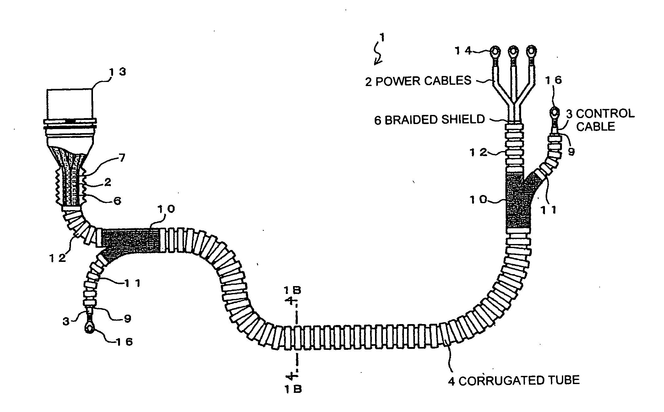
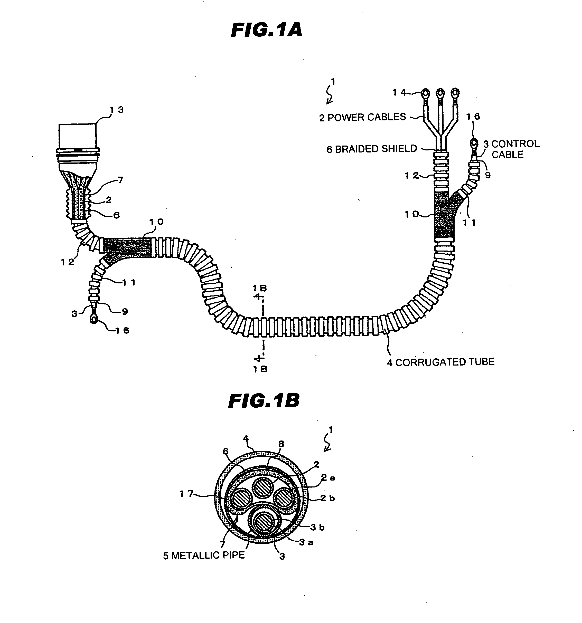
FIG. 1A is a plan view showing a vehicle electrical conduction path in a first preferred embodiment according to the invention, and FIG. 1B is a cross-sectional view taken along line 1B-1B in FIG. 1A.
(Structure of a Vehicle Electrical Conduction Path 1)
A vehicle electrical conduction path 1 in the first preferred embodiment according to the invention comprises a plurality of power cables 2, a braided shield 6 for bundling and shielding the plural power cables 2, at least one control cable 3, a metallic pipe 5 for being formable or moldable into a desired shape into which the control cable 3 is accommodated; and a corrugated tube 4 for serving as a flexible resin tube, wherein the plural power cables 2 bundled with the braided shield 6 are arranged along the metallic pipe 5, and a periphery thereof is covered with the corrugated tube 4.
In other words, the vehicle electrical conduction path 1 comprises the power cables 2, the braided shield 6 which bundles and shields the plural power...
second embodiment
A second preferred embodiment according to the invention is described next.
(Vehicle Electrical Conduction Path 91)
Referring to FIG. 9, a vehicle electrical conduction path 91 is basically configured as with the vehicle electrical conduction path 1 shown in FIGS. 1A and 1B, but the arrangement and shape of the power cables 2 (the shape of the power cable bundle 7) are different therefrom.
Although the vehicle electrical conduction path 1 shown in FIGS. 1A and 1B has the three power cables 2 arranged in a substantially C-shape in its cross-sectional view along a periphery of the metallic pipe 5, the vehicle electrical conduction path 91 of FIG. 9 has the power cable bundle 7 formed of the three power cables 2 bundled in a substantially triangular shape in its cross-sectional view, and arranged along one side of the metallic pipe 5. When the horizontal direction in FIG. 9 is the width direction of the vehicle electrical conduction path 91, and the vertical direction in FIG. 9 is the hei...
third embodiment
(Modifications to the Third Embodiment)
(Vehicle Electrical Conduction Path 121)
A vehicle electrical conduction path 121 in a modification to the third preferred embodiment according to the invention is described next.
FIG. 12 is a cross-sectional view showing the vehicle electrical conduction path 121 in the modification to the third embodiment according to the invention.
The vehicle electrical conduction path 121 shown in FIG. 12 is basically configured as with the vehicle electrical conduction path 111 of FIG. 11, but differs therefrom in that the insulating layer (sheath) 30 is extruded and formed to cover the braided shield 6. In this case, in order for the insulating layer 30 to uniformly cover the braided shield 6, it is preferable that a filler 28 be interposed between the power cables 2, and that the power cable bundle 7 be formed in a substantially circular shape in its cross-sectional view. The filler 28 may use a polypropylene string, for example.
(Vehicle Electrical Conduct...
PUM
| Property | Measurement | Unit |
|---|---|---|
| Length | aaaaa | aaaaa |
| Length | aaaaa | aaaaa |
| Thickness | aaaaa | aaaaa |
Abstract
Description
Claims
Application Information