
Vehicle lighting display system

a display system and vehicle technology, applied in fixed installation, lighting and heating equipment, instruments, etc., can solve the problems of limited customization, color variation, and limited customization of the level of the operator, and achieve the effect of increasing the steepness

Active Publication Date: 2011-06-30
BRANT GREGORY S
View PDF10 Cites 19 Cited by
  • Summary
  • Abstract
  • Description
  • Claims
  • Application Information

AI Technical Summary

Benefits of technology

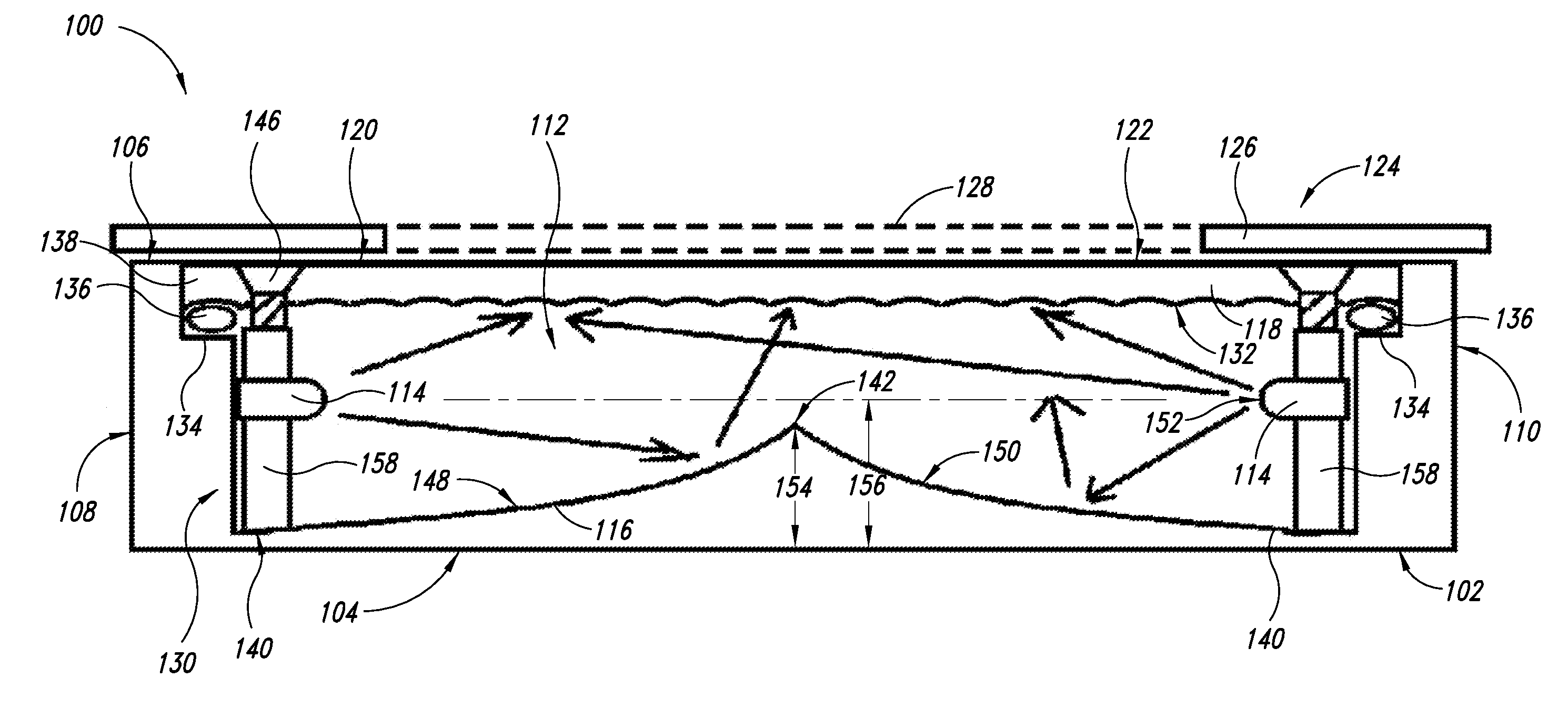
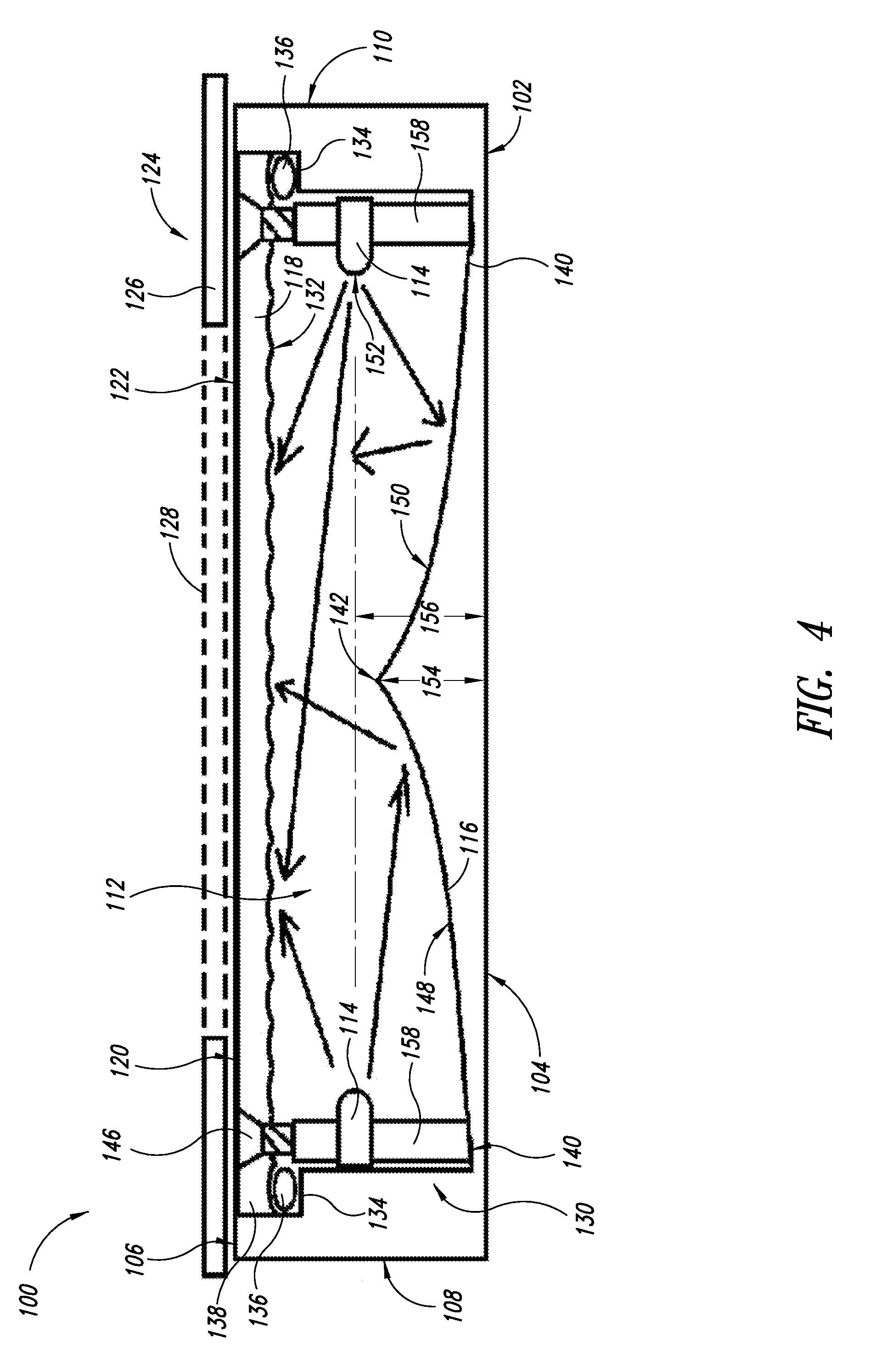
[0021]In accordance with a further aspect of the present disclosure, the reflector has a shallow inverted V shape, a peak of the V extending along a central axis of a length of the housing and a slope of sides of the V increasing in steepness as the sides approach the peak. The faceplate has an opaque region and the transparent pattern, wherein the opaque region covers a portion of the housing where the light sources are mounted. The transparent pattern is configured to be uniformly backlit by the plurality of light sources.
[0022]In accordance with another embodiment of the present disclosure, an apparatus is provided that includes a vehicle and a lighting system coupled to the vehicle. The lighting system includes a housing coupled to the vehicle, the housing having a front panel and a back panel, the front panel having an opening; a reflector in the housing positioned adjacent the back panel; a plurality of light sources in the housing positioned on sides of the housing that are transverse to the back panel; a lens positioned in the housing between the plurality of light sources and the front panel; a plurality of fasteners configured to couple the lens to the housing; a faceplate configured to couple to the housing adjacent the front panel, the faceplate having a pattern; a controller coupled to the light sources having a first input coupled to a vehicle ignition switch and a second input coupled to an accessory switch; and a color mapping interface coupled to the controller and configured to receive at least one removable color chip, the controller configured to detect at least one color signal from the at least one removable color chip and to control the plurality of light sources in response to the at least one detected color signal.

Problems solved by technology

The decorative value, color variation, and level of customization are limited by the D.O.T. color restrictions.
These fixed colors and fixed shape arrangements also have limited customization because of the above-described D.O.T. color restrictions.
The use of single color LEDs limits the degree to which the operator can customize and later change the color of emitted light.
Single color LEDs can display only one color, so the operator is not able to have the lights cycle between two selected colors.
It is generally not feasible for manufacturers or suppliers to make and stock many subtle variations of hues, such as reddish purple or bluish purple.
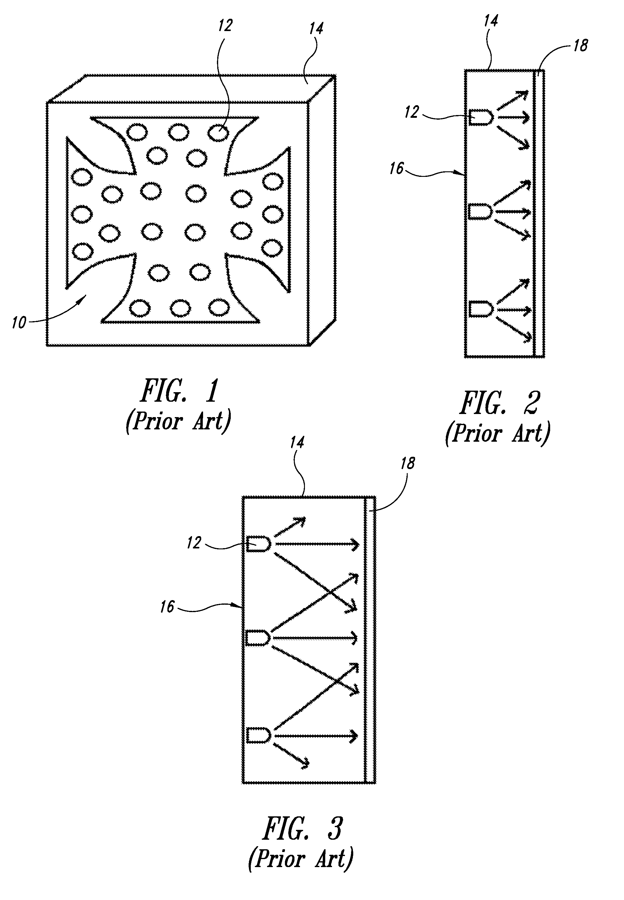
Thus, while a line-of-sight, fixed-LED approach may maximize brightness, the patterns of lights emitted are limited to rudimentary designs and patterns.
The operator cannot select the colors they want and often results in undesired colors being displayed.
Thus, the operator is not able to customize the colors in the cycle to match vehicle paint colors, company colors, product advertising colors, favorite sports teams, or to celebrate a holiday.
Equipping a fleet of vehicles with an illuminated design of a company logo is difficult because each vehicle should have the same color or mix of color light emitted.
With current control schemes it is difficult to achieve consistency in the control of the color across their fleet of vehicles.
In addition, it is time-consuming to set the amount of light emitted by the multicolor light sources of each vehicle in the fleet to achieve the desired hue not only initially, but whenever a new color is to be displayed.
It is also difficult to get a color consistently repeated across each vehicle in the fleet, as manually setting the color mix visually is subject to variations in the settings when the process is repeated numerous times. This problem is compounded when the vehicles are geographically separated so that using one as a visual reference for another is not possible.

Method used


Image

  • Vehicle lighting display system
  • Vehicle lighting display system
  • Vehicle lighting display system

Examples


Embodiment Construction

[0043]In the following description, certain specific details are set forth in order to provide a thorough understanding of various disclosed embodiments. However, one skilled in the relevant art will recognize that embodiments may be practiced without one or more of these specific details, or with other methods, components, materials, etc. In other instances, well-known structures or components or both associated with vehicles have not been shown or described in order to avoid unnecessarily obscuring descriptions of the embodiments.

[0044]Unless the context requires otherwise, throughout the specification and claims that follow, the word “comprise” and variations thereof, such as “comprises” and “comprising” are to be construed in an open inclusive sense, that is, as “including, but not limited to.” The foregoing applies equally to the words “including” and “having.”

[0045]Reference throughout this description to “one embodiment” or “an embodiment” means that a particular feature, str...


PUM


Abstract

A lighting system for vehicles includes a housing having a front panel and a back panel, a reflector positioned adjacent the back panel, a plurality of light sources positioned on sides of the housing transverse to the back panel, a lens positioned the plurality of light sources and the front panel, a faceplate having a transparent pattern is configured to couple to the housing adjacent the front panel, a controller coupled to the light sources having a first input configured to couple to a vehicle ignition switch and a second input configured to couple to an accessory switch, and a color mapping interface coupled to the controller and configured to receive at least one removable color chip. The controller detects at least one color signal from the at least one removable color chip and controls the plurality of light sources in response to the at least one detected color signal.

Description

BACKGROUND[0001]1. Technical Field[0002]The present disclosure relates to accessory lighting for vehicles and, more particularly, to a system for illuminating a user-selected pattern on a vehicle light display that automatically switches from a user-selected color or colors to a government approved color scheme when the vehicle's engine is turned on.[0003]2. Description of the Related Art[0004]The durability, brightness, small size, and low current draw make light-emitting diodes (LEDs) useful for motor vehicle applications beyond the required exterior motor vehicle lighting. However, governmental regulators such as the U.S. Department of Transportation (D.O.T.) limit the colors of exterior vehicle lights that may be illuminated when the vehicle is operated on the highways in order to enhance highway safety. The D.O.T. generally prohibits the use of colors other than red, amber, or white while a vehicle is operated on a road so operators of other vehicles (such as automobiles, motor...

Claims


Application Information

Patent Timeline
Patent Type & Authority Applications(United States)
IPC IPC(8): B60Q1/14F21S8/10
CPCB60Q1/50F21V7/00F21Y2101/02G09F13/005G09F13/18G09F13/22G09F2013/145G09F13/14F21Y2115/10
Inventor BRANT, GREGORY S.
Owner BRANT GREGORY S
Learn More