
Soot Sensor

a sensor and sensor technology, applied in the field of soot sensors, can solve problems such as the change of the electrical resistance of the substrate, and achieve the effects of high measurement sensitivity, high precision, and robust electrode structur

Inactive Publication Date: 2011-06-30
CONTINENTAL AUTOMOTIVE GMBH
View PDF11 Cites 27 Cited by
  • Summary
  • Abstract
  • Description
  • Claims
  • Application Information

AI Technical Summary

Benefits of technology

[0017]In another configuration, the structure of measurement electrodes engaging interdigitally in one another is constructed from thin-film electrodes. Very fine structures can be produced with high precision by thin-film methods, which makes it possible to produce a soot sensor with a high measurement sensitivity.

Problems solved by technology

First, the change in the temperature of the soot sensor both due to the hot exhaust gases and during the heating to regenerate the structure of the measurement electrodes, entails a change in the electrical resistance of the substrate.

Method used


Image

  • Soot Sensor
  • Soot Sensor
  • Soot Sensor

Examples


Embodiment Construction

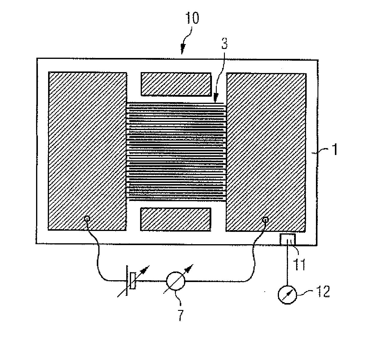
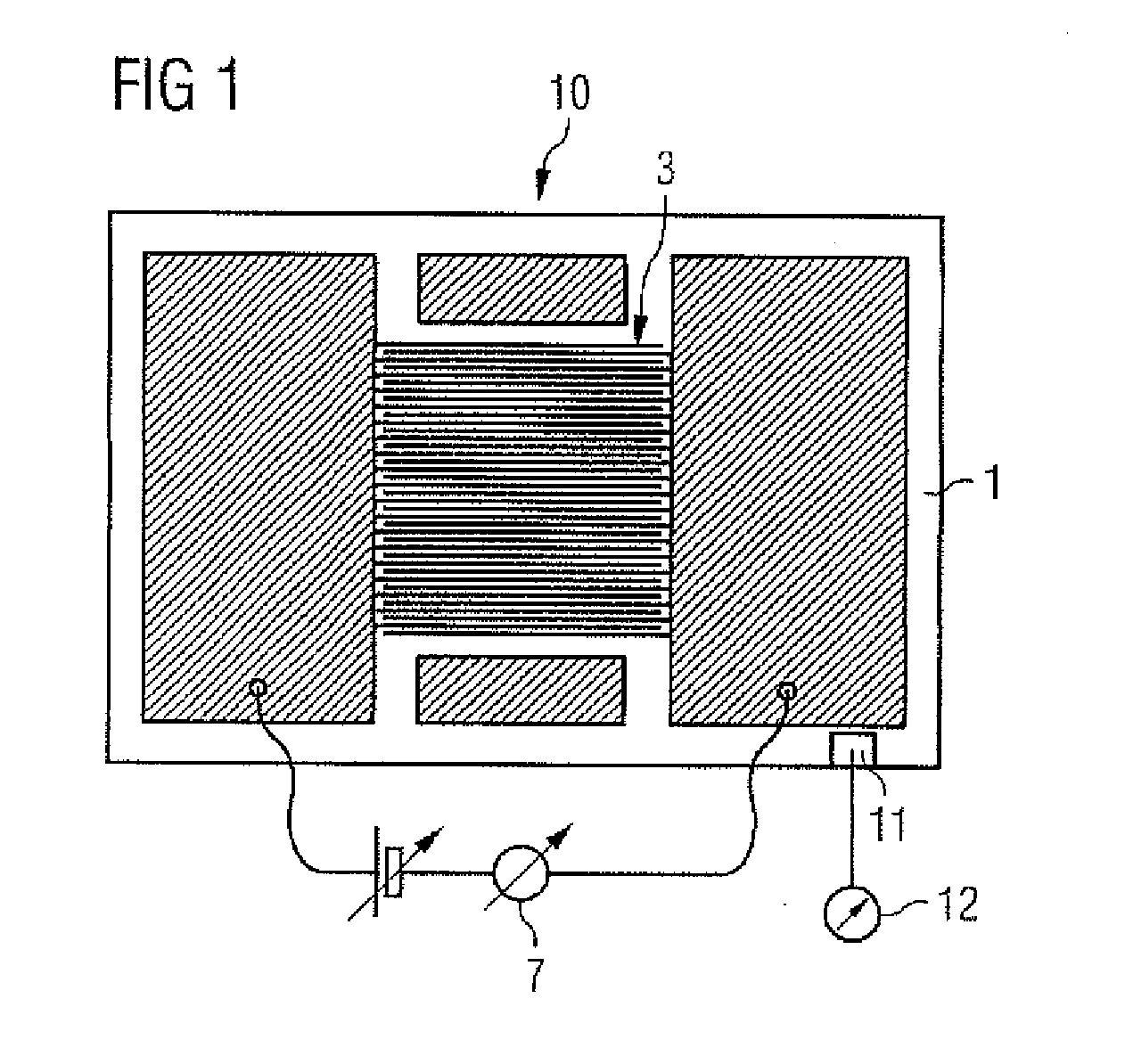
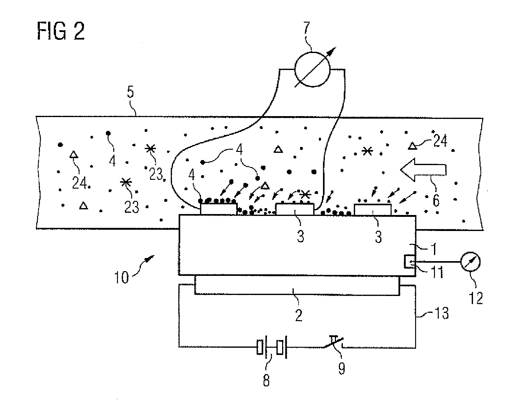
[0026]FIG. 1 shows a soot sensor 10 which is constructed from a substrate 1, a heating element 2 (FIG. 2) and a structure of measurement electrodes 3. The substrate 1 may be made of a ceramic material, or of another material which has electrically insulating properties and readily withstands the burn-off temperature of soot. In order to free the soot sensor 10 of soot by burning, the soot sensor 10 is typically heated with the aid of an electrical heating resistor to temperatures of between 500 and 800° C. The electrically insulating substrate 1 must tolerate these temperatures without damage. The structure of the measurement electrodes 3 is formed as a comb-like (interdigital) structure, an electrically insulating region of the substrate 1 always being visible between two measurement electrodes. The flow of current between the electrode structures is measured with the aid of a current measuring element 7. So long as the soot sensor 10 is entirely free of soot particles 4, only a ve...


PUM


Abstract

A soot sensor for the detection of soot particles in an exhaust gas flow, having interdigitally engaged measurement electrodes applied on a substrate. An electrical resistance between the measurement electrodes is a measure of soot load of the exhaust gas flow. The measurement electrodes are divided into two regions, a first region in which no soot particles can be deposited and a second region where soot particles are deposited from the exhaust gas flow. The first region and the second region are exposed simultaneously to the other conditions prevailing in the exhaust gas flow.

Description

BACKGROUND OF THE INVENTION[0001]1. Field of the Invention[0002]The invention relates to a soot sensor configured to detect soot particles in an exhaust gas flow having a structure comprising measurement electrodes engaging interdigitally with one another, which are applied on a substrate, the electrical resistance between the measurement electrodes being measured as a measure of a soot load of the exhaust gas flow.[0003]2. Description of the Related Art[0004]The buildup of pollutants from exhaust gases in the atmosphere is a topic of great discussion at present. Associated with this is the fact that the availability of fossil energy sources is limited. In response to this combustion processes in internal combustion engines are being thermodynamically optimized to improve their efficiency. In the automotive sector, this is reflected in the increasing use of diesel engines. The disadvantage of this combustion technology in relation to optimized gasoline engines, however, is a signifi...

Claims


Application Information

Patent Timeline
Patent Type & Authority Applications(United States)
IPC IPC(8): G01R27/08G01M15/10
CPCF02D41/1466Y02T10/40G01N15/0656F02D41/222
Inventor ACHHAMMER, ROLANDANTE, JOHANNESBIERL, RUDOLFHEINRICH, STEPHANHERRMANN, MARKUSLAUERER, WOLFGANGOTT, ANDREASREITMEIER, WILLIBALDSCHADLICH, DENNYWEIGL, MANFREDWILDGEN, ANDREAS
Owner CONTINENTAL AUTOMOTIVE GMBH
Learn More