Eureka AIR delivers breakthrough ideas for toughest innovation challenges, trusted by R&D personnel around the world.

Video encoding apparatus and video decoding apparatus

Inactive Publication Date: 2011-06-30
KDDI R&D LAB INC
View PDF7 Cites 1 Cited by
  • Summary
  • Abstract
  • Description
  • Claims
  • Application Information

AI Technical Summary

Benefits of technology

[0028]With the present invention, the interpolation filter can be determined without involving large amounts of operations. Thus, such an arrangement provides real-time processing having improved coding performance.

Problems solved by technology

As described above, the methods described in Thomas Wedi, and Yuri Vatis and Joern Ostermann, require a large amount of operations, leading to a long processing time.
However, in a case in which an adaptive interpolation filter is applied, in some cases, such an arrangement is not capable of providing such real-time processing.

Method used


Image

  • Video encoding apparatus and video decoding apparatus
  • Video encoding apparatus and video decoding apparatus
  • Video encoding apparatus and video decoding apparatus

Examples


first embodiment

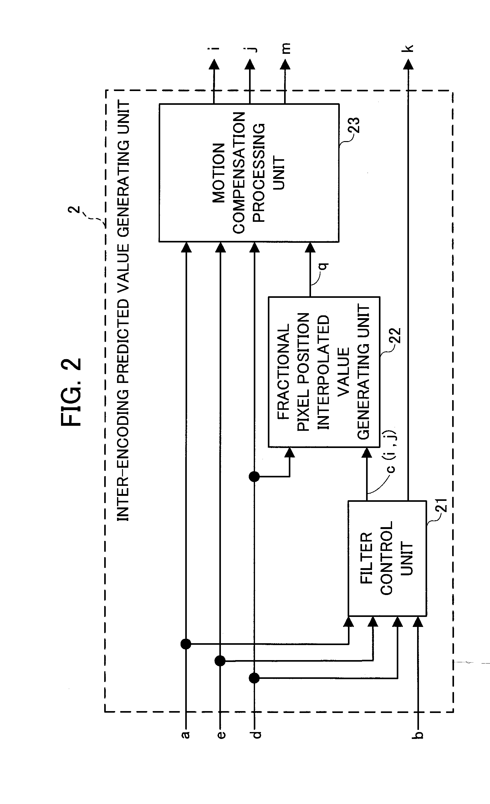
[0047]Description will be made below regarding a first method employed in the aforementioned filter control unit 21. With the first method, the tap size N of the interpolation filter and the initial value c0(i,j) of the filter coefficient of the interpolation filter are extracted from the interpolation filter initial control information b. The initial value c0(i,j) of the filter coefficient of the interpolation filter thus extracted is determined as the filter coefficient c(i,j) of the interpolation filter. Subsequently, the filter coefficient c(i,j) of the interpolation filter thus determined and the interpolation filter control information k are output. It should be noted that the interpolation filter control information k includes the tap size N of the interpolation filter and the initial value c0(i,j) of the filter coefficient of the interpolation filter.

[Configuration of Video Decoding Apparatus BB]

[0048]FIG. 3 is a block diagram which shows a configuration of a video decoding ...

second embodiment

[Configuration of Video Encoding Apparatus CC]

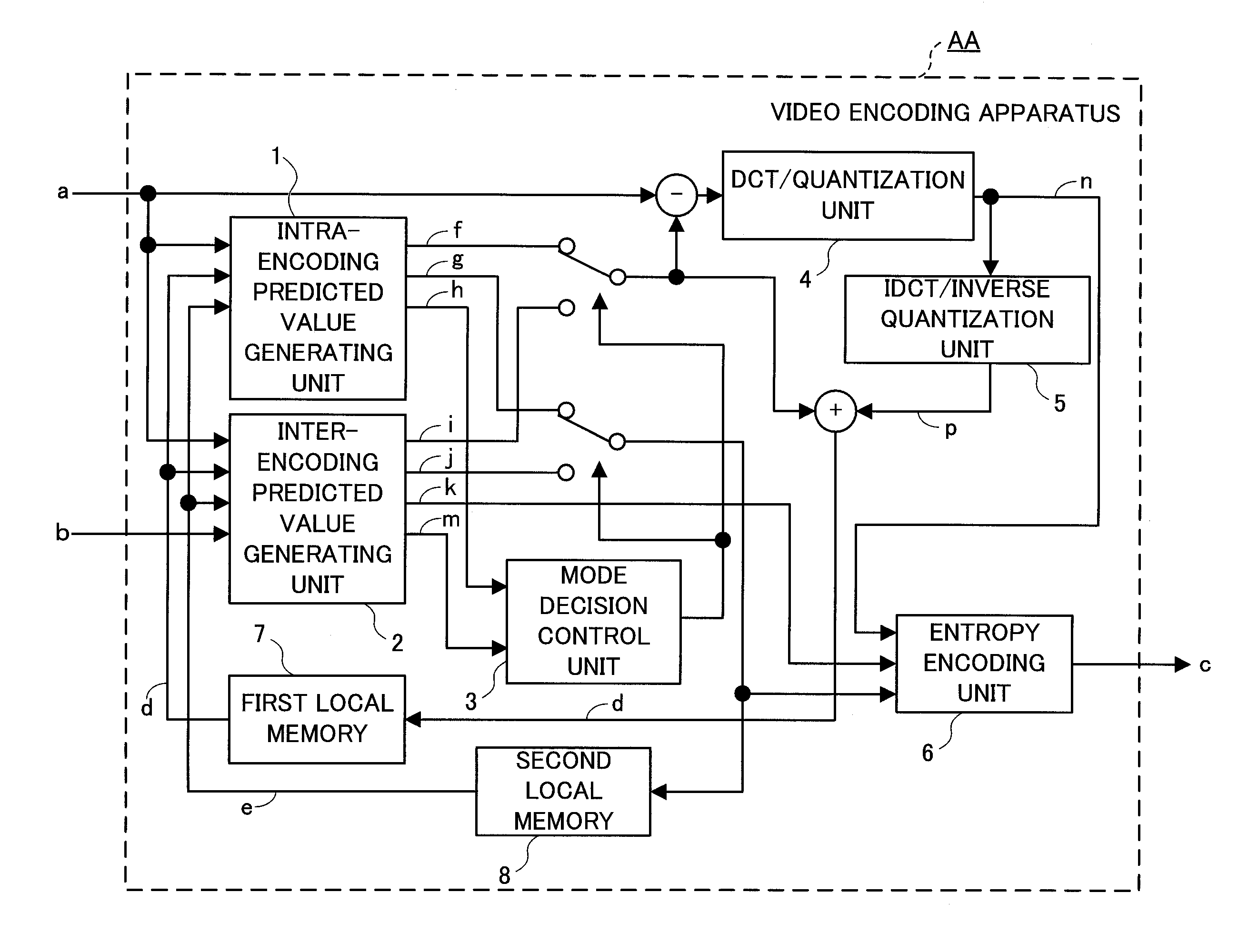
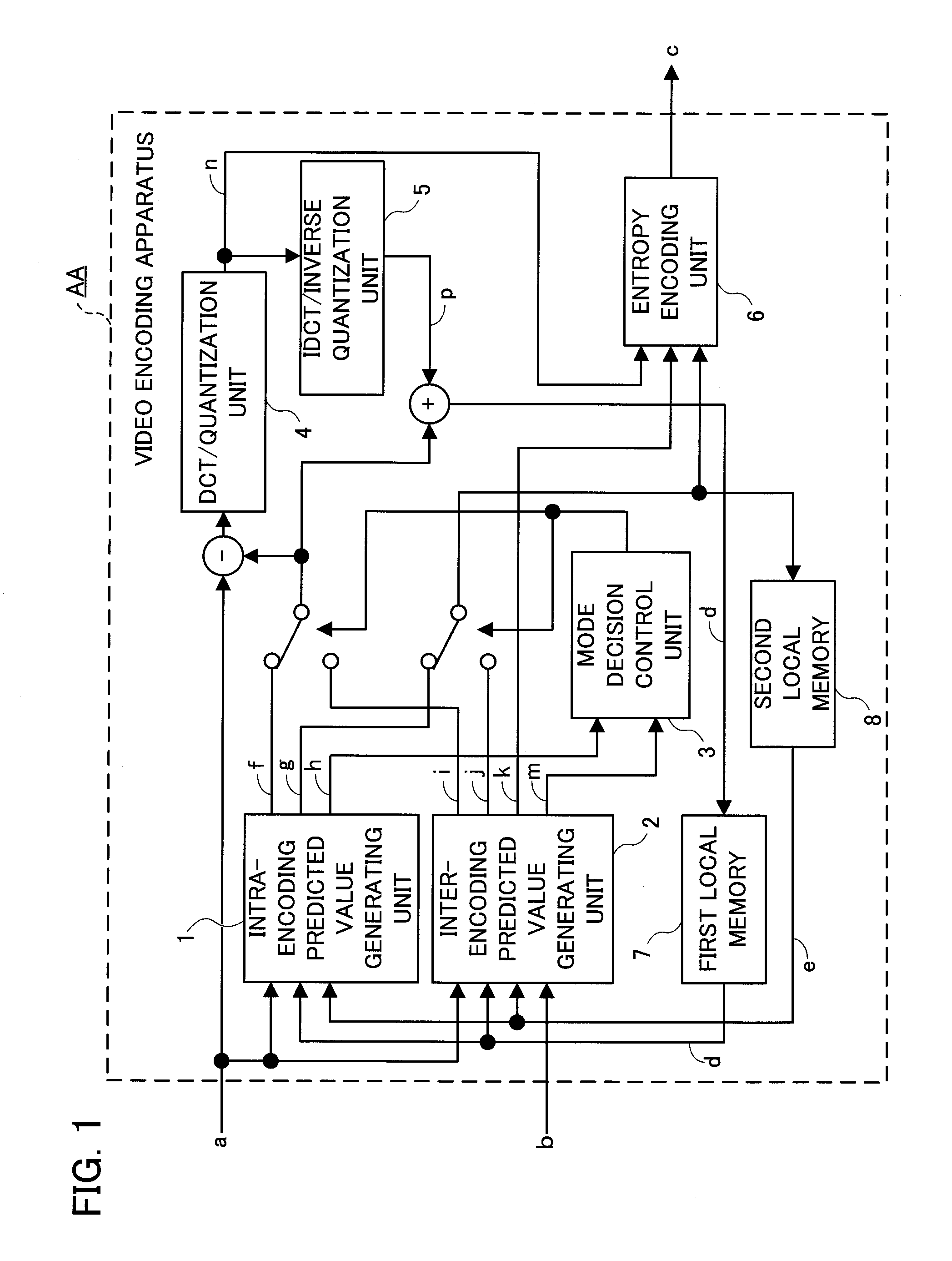
[0062]Description will be made below regarding a video encoding apparatus CC according to a second embodiment of the present invention. The video encoding apparatus CC has the same configuration as that of the video encoding apparatus AA according to the first embodiment of the present invention shown in FIG. 1. With regard to the video encoding apparatus CC, the same components as those of the video encoding apparatus AA are denoted by the same reference numerals, and description thereof will be omitted. It should be noted that the filter control unit 21 of the video encoding apparatus AA determines the filter coefficient c(i,j) of the interpolation filter using the aforementioned first method. In contrast, the filter control unit 21 of the video encoding apparatus CC determines the filter coefficient c(i,j) of the interpolation filter using a third method described later.

[Third Method]

[0063]With the third method, first, the pixel value...

third embodiment

[Configuration of Video Encoding Apparatus EE]

[0076]Description will be made below regarding a video encoding apparatus EE according to a third embodiment of the present invention. The video encoding apparatus EE has the same configuration as that of the video encoding apparatus AA according to the first embodiment of the present invention shown in FIG. 1. With regard to the video encoding apparatus EE, the same components as those of the video encoding apparatus AA are denoted by the same reference numerals, and description thereof will be omitted. It should be noted that the filter control unit 21 of the video encoding apparatus AA determines the filter coefficient c(i,j) of the interpolation filter using the aforementioned first method. In contrast, the filter control unit 21 of the video encoding apparatus EE determines the filter coefficient c(i,j) of the interpolation filter using a fifth method described later.

[Fifth Method]

[0077]With the fifth method, first, the inter-pixel ...


PUM


Abstract

It is a purpose of the present invention to provide a video encoding apparatus and a video decoding apparatus which are capable of providing real-time processing having improved coding performance. A video encoding apparatus AA includes an inter-encoding predicted value generating unit 2 configured to receive, as input signals, an input image a, a local decoded value d acquired from an encoded block, prediction direction information e acquired from the encoded block, and interpolation filter initial control information b. The inter-encoding predicted value generating unit 2 includes a filter control unit 21. The filter control unit 21 extracts the tap size N of the interpolation filter and the initial value c0(i,j) of the filter coefficient of the interpolation filter from the interpolation filter initial control information b, and uses the initial value c0(i,j) of the filter coefficient of the interpolation filter as the filter coefficient c(i,j) of the interpolation filter.

Description

[0001]This application is based on and claims the benefit of priority from Japanese Patent Application No. 2009-294618, filed on 25 Dec. 2009, the content of which is incorporated herein by reference.BACKGROUND OF THE INVENTION[0002]1. Field of the Invention[0003]The present invention relates to a video encoding apparatus configured to encode a video and a video decoding apparatus configured to decode a video encoded by the video encoding apparatus.[0004]2. Description of the Related Art[0005]Conventional techniques have been proposed which allow inter-frame prediction to be performed when a video is encoded (see Joint Video Team (JVT) of ISO / IEC MPEG and ITU-T VCEG, “Text of ISO / IEC 14496-10 Advanced Video Coding”, July 2004, for example). With such inter-frame prediction, a region having a pattern similar to that of an encoding target region is detected from an image which has already been encoded, and the pixel values of the region thus detected are used as the predicted value of...

Claims


Application Information

Patent Timeline
IPC IPC(8): H04N7/26H04N19/50H04N19/117H04N19/136H04N19/162H04N19/196H04N19/423H04N19/46H04N19/503H04N19/51H04N19/523H04N19/59H04N19/593H04N19/61H04N19/625H04N19/70H04N19/80H04N19/91
CPCH04N19/139H04N19/176H04N19/523H04N19/117H04N19/61
Inventor YOSHINO, TOMONOBUNAITO, SEISAKAZAWA, SHIGEYUKI
Owner KDDI R&D LAB INC
Why Eureka
Eureka Blog
Learn More