Visualization Apparatus for PEMFC Stack

a technology of visualization apparatus and pemfc, which is applied in the direction of fuel cell details, instruments, electrochemical generators, etc., can solve the problem that the visualization apparatus has not yet been developed to visualiz

Inactive Publication Date: 2011-06-30
KOREA ADVANCED INST OF SCI & TECH
View PDF10 Cites 3 Cited by
  • Summary
  • Abstract
  • Description
  • Claims
  • Application Information

AI Technical Summary

Benefits of technology

[0012]According to the visualization apparatus for the PEMFC stack, it is possible to visualize the PEMFC approximating the car or the household power generation system used in the stack form in which the real unit cells are stacked.
[0013]The present invention can observe the change in visual flow and voltage for each unit cell in the stack, thereby making it possible to analyze the unit cell in the assembled state of the stack in the PEMFC.

Problems solved by technology

Generally, the visualization apparatus can visualize only the individual unit cells, but the visualization apparatus has not yet been developed to visualize the entire stack or the unit cells after being assembled into the stack.

Method used


Image

  • Visualization Apparatus for PEMFC Stack
  • Visualization Apparatus for PEMFC Stack
  • Visualization Apparatus for PEMFC Stack

Examples


Embodiment Construction

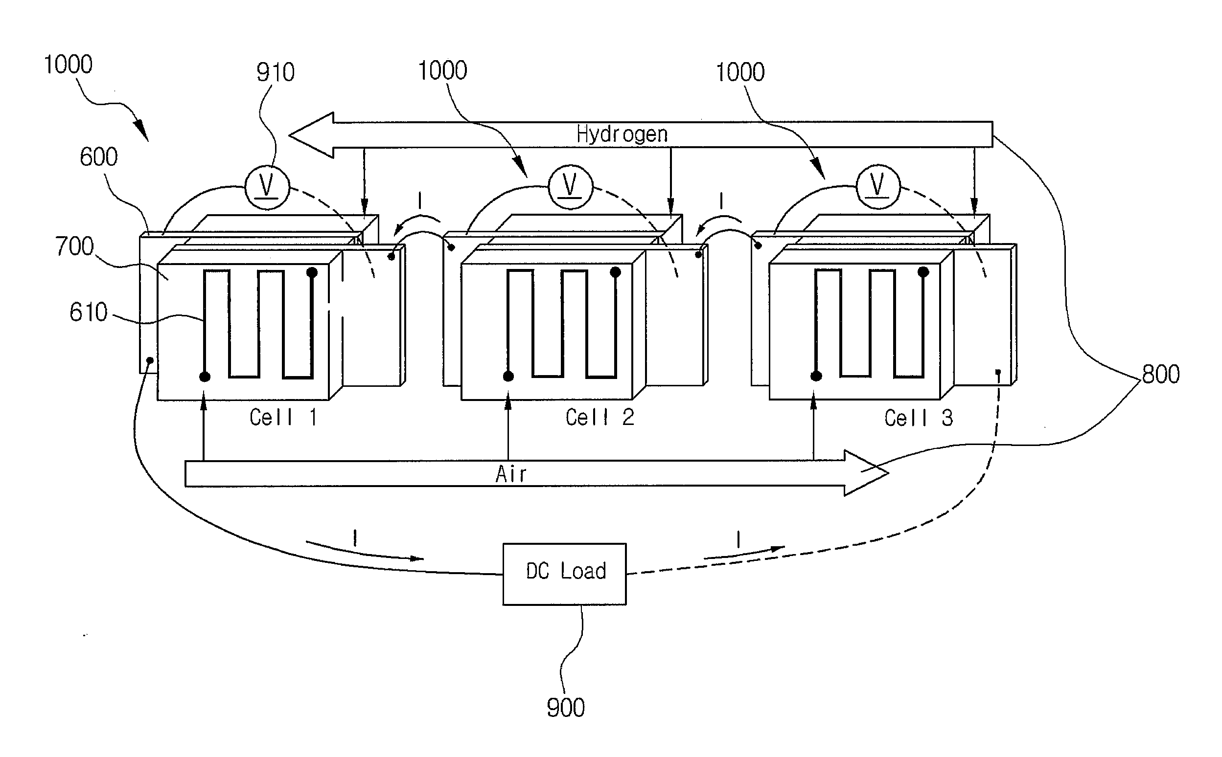
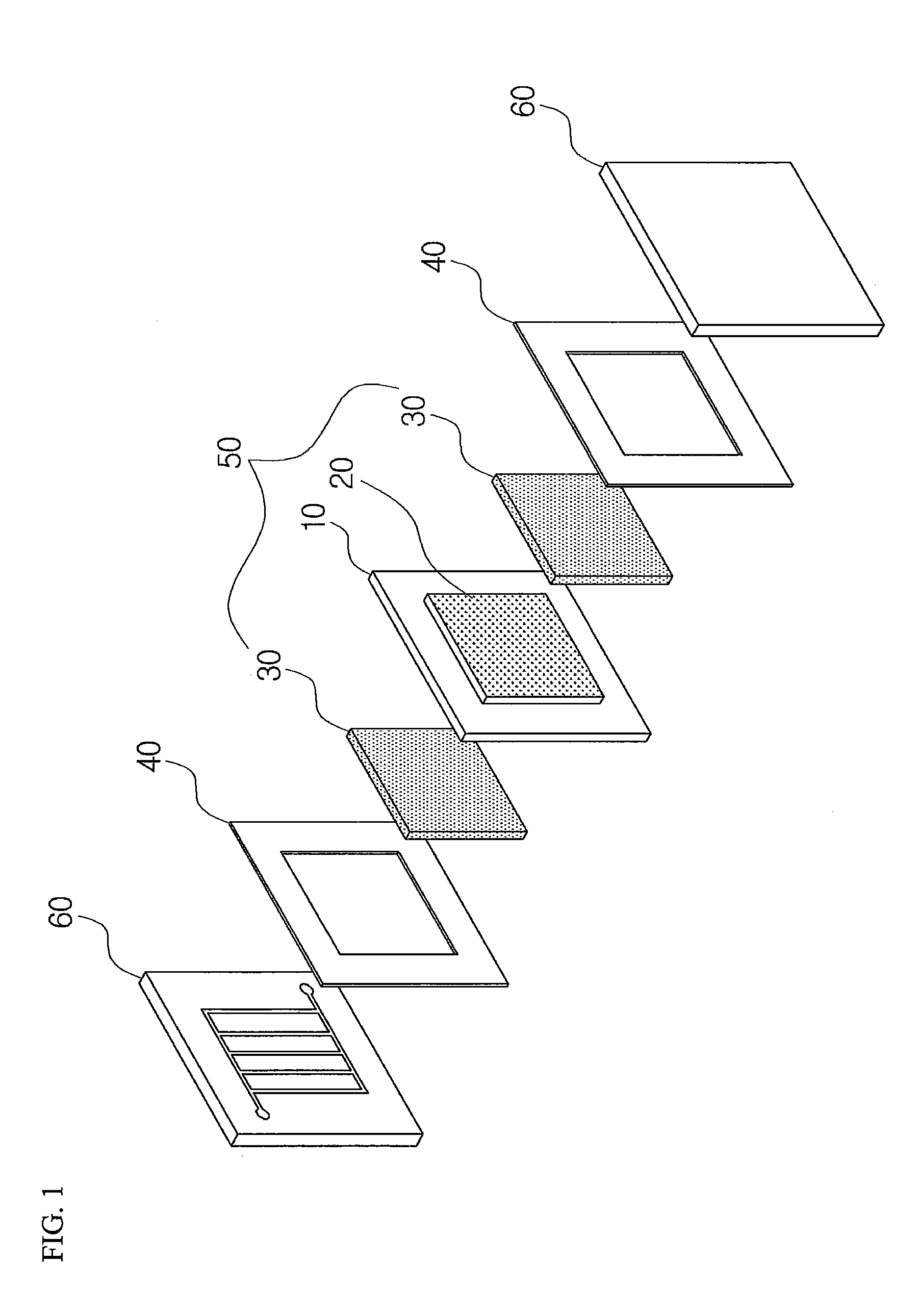
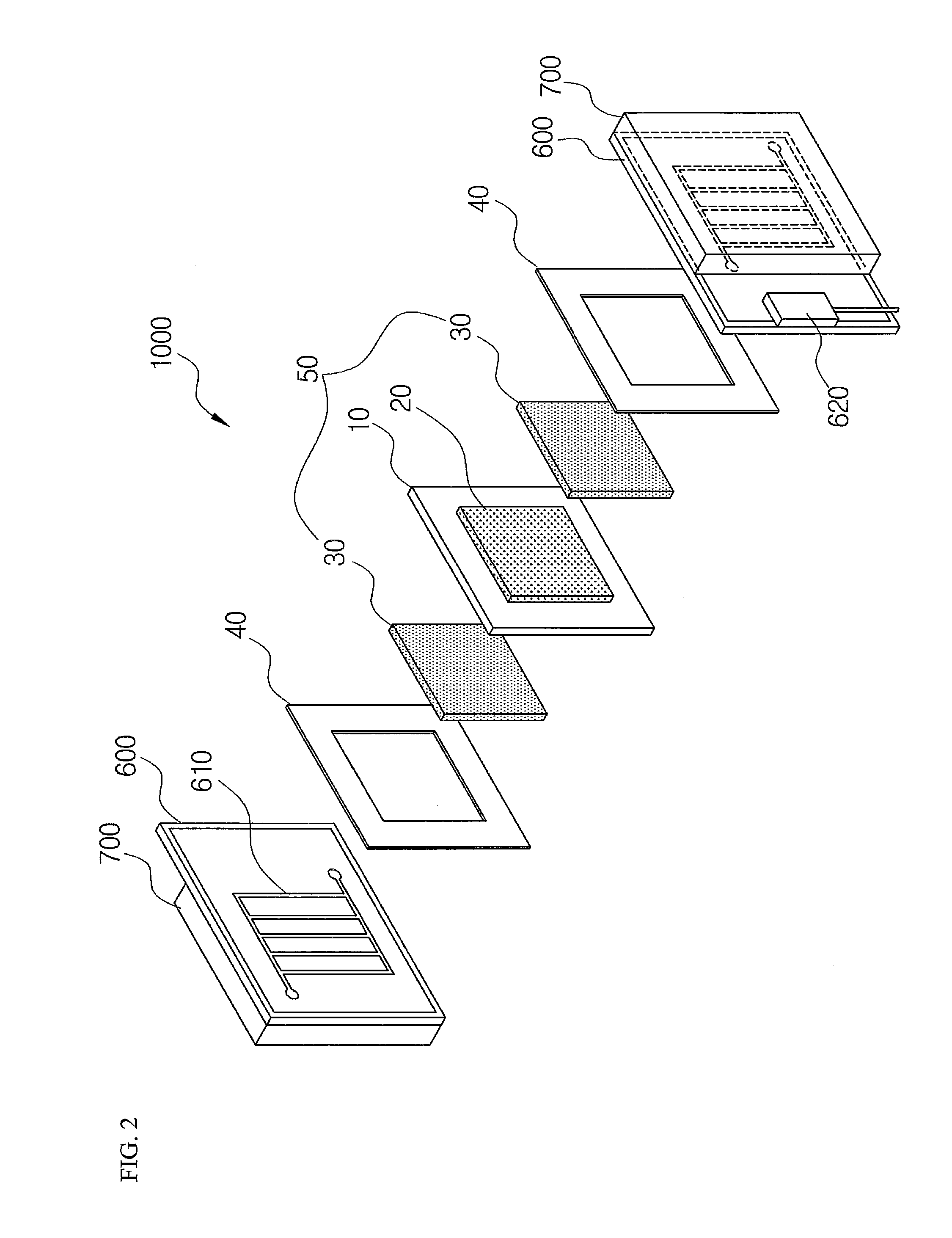
[0019]10: POLYMER ELECTROLYTE MEMBRANE[0020]20: CATALYST LAYER[0021]30: GAS DIFFUSION LAYER[0022]40: GASKET[0023]50: MEMBRANE ELECTRODE ASSEMBLY[0024]60: SEPARATOR[0025]600: CURRENT COLLECTOR PLATE[0026]610: CHANNEL[0027]700: TRANSPARENT PLATE[0028]800: FUEL DISTRIBUTION STRUCTURE[0029]900: PEMFC STACK VOLTAGE MEASURING UNIT[0030]910: UNIT CELL MONITORING UNIT[0031]1000: VISUALIZATION APPARATUS FOR UNIT CELL[0032]2000: VISUALIZATION APPARATUS FOR PEMFC STACK

BEST MODE

[0033]Hereinafter, a visualization apparatus for a PEMFC according to the present invention will be described in detail with reference to the accompanying drawings.

[0034]FIG. 2 is a shape of a visualization apparatus for a unit cell. FIG. 3 is a shape of a PEMFC stack in which unit cells are stacked and FIG. 4 is a configuration diagram of the visualization apparatus for a PEMFC stack according to the present invention.

[0035]As shown in FIG. 2, unlike a real PEMFC, a visualization apparatus 1000 for a unit cell includes ...


PUM

PropertyMeasurementUnit
operating temperatureaaaaaaaaaa
thicknessaaaaaaaaaa
voltageaaaaaaaaaa

Abstract

Provided is a visualization apparatus for a PEMFC stack using a transparent window. More particularly, provided is a visualization apparatus for a PEMFC stack including: a plurality of visualization apparatuses for unit cells including current collector plates each provided on both sides of a membrane electrode assembly of a PEMFC and formed with channels through which reaction gas and products flow and a transparent plate provided on the outer surface of the current collector plate. Provided is a visualization apparatus for a PEMFC stack electrically connecting the current collector plates of the visualization apparatus for unit cells to each other in series.

Description

TECHNICAL FIELD[0001]The present invention relates to a visualization apparatus for a PEMFC stack using a transparent window, and more particularly, to a visualization apparatus for a PEMFC stack capable of having conditions approximating a real PEMFC by implementing a single PEMFC stack by electrically connecting a plurality of visualization apparatuses for unit cells in series and connecting them to each other in parallel in distributing fuel.BACKGROUND ART[0002]As environmental regulations of automobile markets are increasingly tightened, the world's carmakers have tried to develop environment-friendly and high-efficient cars. It is expected that the fuel-cell car will emerge as the center focus of an automobile market in the future because it is environmentally friendly in that it only discharges water while having high efficiency. As a result, many carmakers have continued to develop a fuel-cell car. A demand for a fuel-cell technology has continuously increased in the industri...

Claims


Application Information

Patent Timeline
Patent Type & Authority Applications(United States)
IPC IPC(8): H01M8/04
CPCY02E60/50H01M8/04305H01M8/02H01M8/10G01R31/36
Inventor BAE, JOONGMYEONLEE, DONGRYUL
Owner KOREA ADVANCED INST OF SCI & TECH
Why Eureka
Try Eureka