Method for measuring polarization characteristics of optical fiber, drawing method, method for identifying abnormal point, and method for configuring optical fiber transmission line

a technology of optical fiber and characteristics, applied in the direction of optical apparatus testing, optical radiation measurement, instruments, etc., can solve the problems of difficult to measure optical fiber characteristics, short beat length, and inconvenient measurement of short beat length, etc., to achieve short beat length and high distance resolution

Inactive Publication Date: 2011-12-13
SUMITOMO ELECTRIC IND LTD
View PDF11 Cites 3 Cited by
  • Summary
  • Abstract
  • Description
  • Claims
  • Application Information

AI Technical Summary

Benefits of technology

[0045]As described above, in accordance with the present invention, Brillouin gain distributions are measured along the longitudinal direction of an optical fiber by using BOCDA. Accordingly, Brillouin distribution measurement with a high distance resolution is possible, and a short beat length (or swing periods, coupling length) or changes in optical fiber characteristics in a short section can be observed. In other words, polarization characteristic distributions along the longitudinal direction of the optical fiber can be measured and calculated. In the measuring method to which BOCDA is applied, by controlling the relative polarization state of the pumping light and the probe light, Brillouin gain fluctuations along the longitudinal direction of the optical fiber are more clearly observed. In other words, polarization characteristic distributions along the longitudinal direction of the optical fiber can be more properly measured. Further, as an applied technique of the measuring technique, abnormal point detection and abnormal point removal are also possible at the optical fiber drawing (manufacturing) step and in a laid optical fiber, and many technical effects can be expected.

Problems solved by technology

However, the distance resolution in the POTDR is generally in a meter order, and this is not suitable for measuring a short beat length and fiber characteristic changes in a short section.
However, even by using the BOFDA, it is difficult to measure optical fiber characteristics such as oscillation of Brillouin gain, that is, beat length relating to PMD with a higher distance resolution.

Method used


Image

  • Method for measuring polarization characteristics of optical fiber, drawing method, method for identifying abnormal point, and method for configuring optical fiber transmission line
  • Method for measuring polarization characteristics of optical fiber, drawing method, method for identifying abnormal point, and method for configuring optical fiber transmission line
  • Method for measuring polarization characteristics of optical fiber, drawing method, method for identifying abnormal point, and method for configuring optical fiber transmission line

Examples


first embodiment

of Polarization Characteristics Measuring Method: FIG. 6

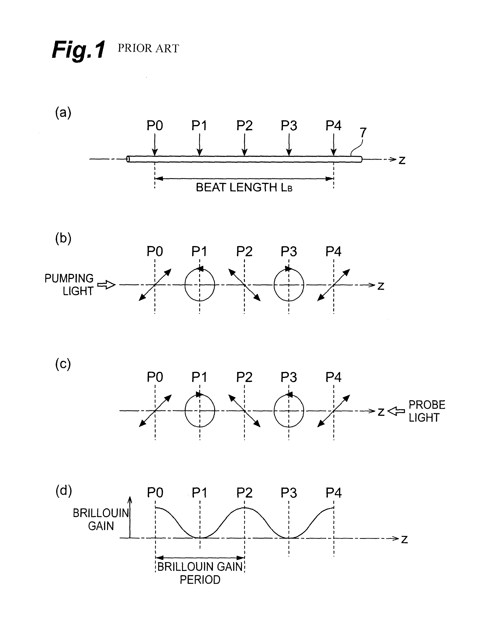
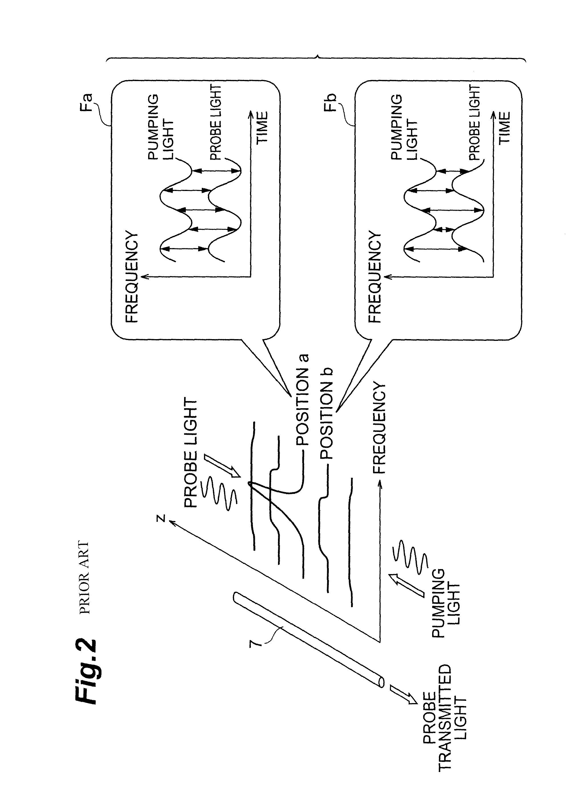
[0071]First, an example of the polarization characteristics measuring method in which according to BOCDA, a BGS is generated at a plurality of measurement positions set along the longitudinal direction of the optical fiber 7 as a measuring object, and based on Brillouin gain fluctuations at the respective measurement positions at which the BGS has been generated, polarization characteristics are calculated, will be described with reference to FIG. 6.

[0072]First, the entire length of the optical fiber 7 as a measuring object, or a predetermined section in the optical fiber 7 is set as a measurement section (section control step S1).

[0073]Next, in the waveform generator 1, by controlling the modulation frequency of the frequency modulation for the light source, the correlation peak position, that is, the measurement position is set within the measurement section (position control step S2). Then, at the correlation peak position, ...

second embodiment

of Polarization Characteristics Measuring Method: FIG. 7

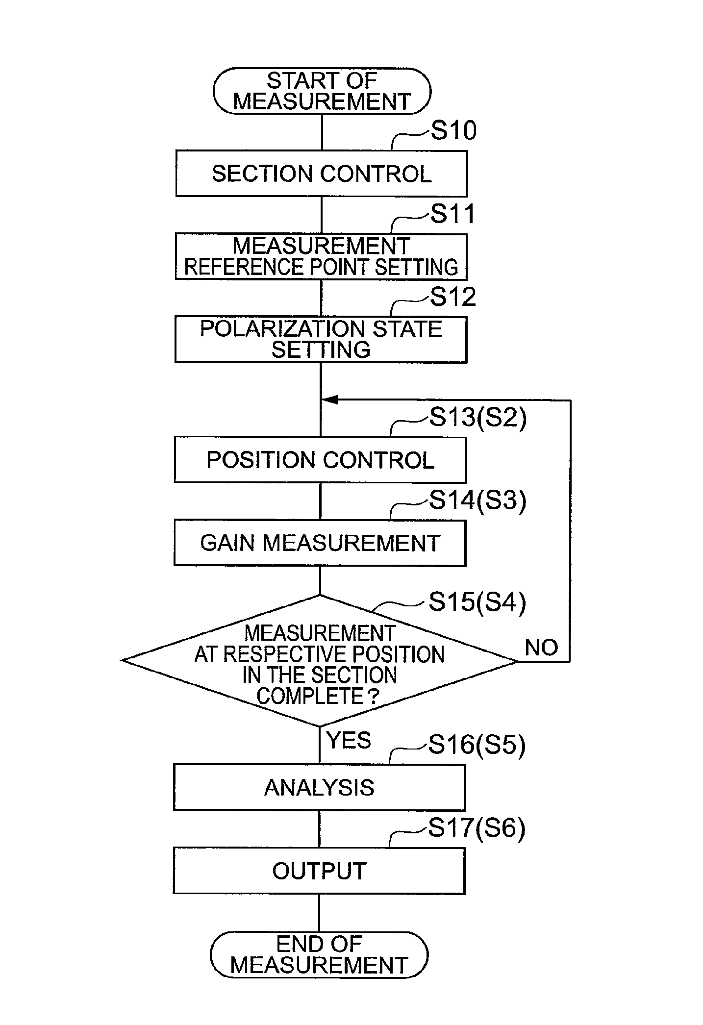
[0076]Next, as a second embodiment of the polarization characteristics measuring method, a case where the incident polarization states of the probe light and the pumping light to be made incident on the optical fiber 7 are controlled so that a measurement reference point at which the Brillouin gain becomes maximum is present in the optical fiber 7 as a measuring object will be described with reference to FIG. 7.

[0077]First, the entire length of the optical fiber 7 as a measuring object or a predetermined section in the optical fiber 7 is set as a measurement section (section control step S10), and a predetermined point within the set measurement section is set as a measurement reference point (measurement position) (measurement reference point setting step S11). Then, by changing the incident polarization state of the pumping light or probe light by the polarization controller (polarization controller 8, 18 in FIG. 4) inserted ...


PUM

PropertyMeasurementUnit
distance resolutionaaaaaaaaaa
radiusaaaaaaaaaa

Abstract

The present invention relates to a measuring method, etc., comprising a structure for accurately measuring optical characteristics such as PMD of an optical fiber. The measuring method is a technique for measuring polarization characteristic distributions along the longitudinal direction of the optical fiber as a measuring object by using BOCDA, and by propagating probe light and pumping light opposite in the optical fiber, BGS is generated at a plurality of respective measurement positions. Then, based on Brillouin gain fluctuations at the respective measurement positions, polarization characteristic distributions are calculated.

Description

RELATED APPLICATIONS[0001]This application is the U.S. National Phase under 35 U.S.C. §371 of International Application No. PCT / JP2008 / 052256, filed on Feb. 12, 2008, which in turn claims the benefit of Japanese Application No. 2007-055738, filed on Mar. 6, 2007, the disclosures of which Applications are incorporated by reference herein.TECHNICAL FIELD[0002]The present invention relates to an optical fiber polarization characteristics measuring method, and relates to an optical fiber drawing method, an abnormal point identifying method, and an optical fiber transmission line establishing method using the polarization characteristics measuring method.BACKGROUND ART[0003]Conventionally, as a factor for limiting increases in speed and distance of an optical fiber communication system, polarization mode dispersion (PMD) is known.[0004]PMD is a phenomenon in which birefringence of an optical fiber causes a differencial group delay between two orthogonal polarization modes propagating ins...

Claims


Application Information

Patent Timeline
Patent Type & Authority Patents(United States)
IPC IPC(8): G01N21/00
CPCC03B37/02745G01M11/319G01M11/336G01M11/39
Inventor YAMAMOTO, YOSHINORISASAOKA, EISUKE
Owner SUMITOMO ELECTRIC IND LTD
Why Eureka
Try Eureka