Visualization apparatus for large area PEMFC

a technology of visualization apparatus and pemfc, which is applied in the direction of cell components, cell component details, instruments, etc., can solve the problems of difficult to know exactly how water is discharged, difficult to know whether or not water is present in anode or cathode state, and expensive apparatus for generating neutron beams

Active Publication Date: 2014-02-11
KOREA ADVANCED INST OF SCI & TECH
View PDF8 Cites 0 Cited by
  • Summary
  • Abstract
  • Description
  • Claims
  • Application Information

AI Technical Summary

Benefits of technology

[0012]According to the visualization apparatus for a large area PEMFC according to the present invention, it is possible to manufacture the visualization apparatus approximating a large area PEMFC applied to a real system. Further, the present invention can perform the flow experiment of the large area PEMFC even in the narrow experimental space.
[0013]In addition, the present invention can observe the change in visual flow and voltage for each unit region, thereby making it possible to analyze the local unit region in the large area PEMFC.

Problems solved by technology

However, since it is difficult to visualize a two-phase flow in the PEMFC channel, research into the flooding has been mainly conducted through interpretation using a CFD.
Even though there is no need to change the components of the PEMFC in order to observe the behavior of water using the neutron beam, and reliability is at the highest, an apparatus generating the neutron beam is very expensive.
In addition, it is difficult to specifically know how water is discharged since a method of processing the image data is complex and the interface of water with air is unclear.
In addition, since the image using the neutron beam is consequently implemented in a two-dimensional plane, it is difficult to know whether or not water is present in an anode or a cathode state.
There is a problem in that the experiment is made in environment different from the real PEMFC.
In order to solve the problem, the large-area visualization apparatus having the substantially same size is manufactured, which largely increases the space and costs.

Method used


Image

  • Visualization apparatus for large area PEMFC
  • Visualization apparatus for large area PEMFC
  • Visualization apparatus for large area PEMFC

Examples


Embodiment Construction

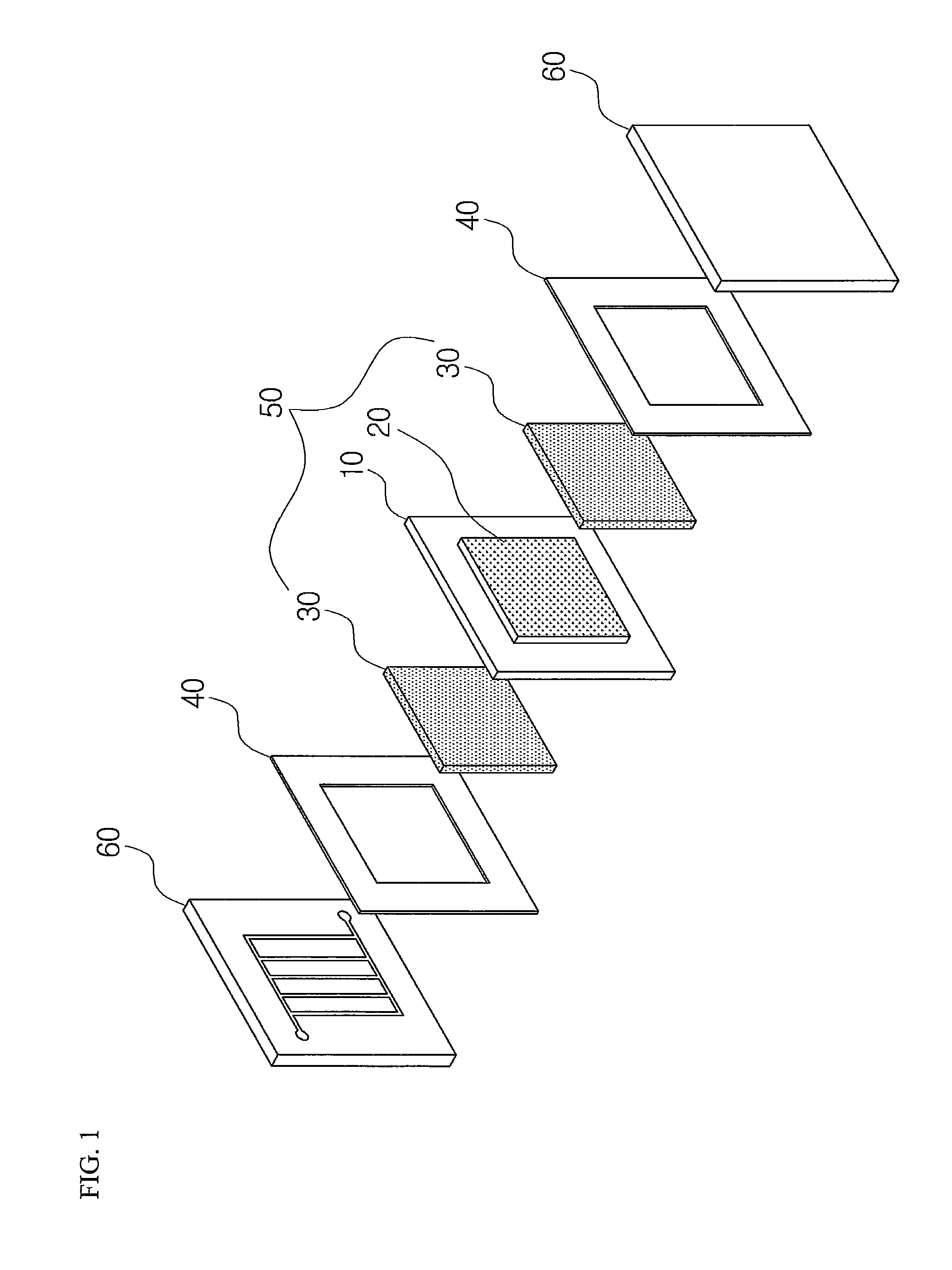
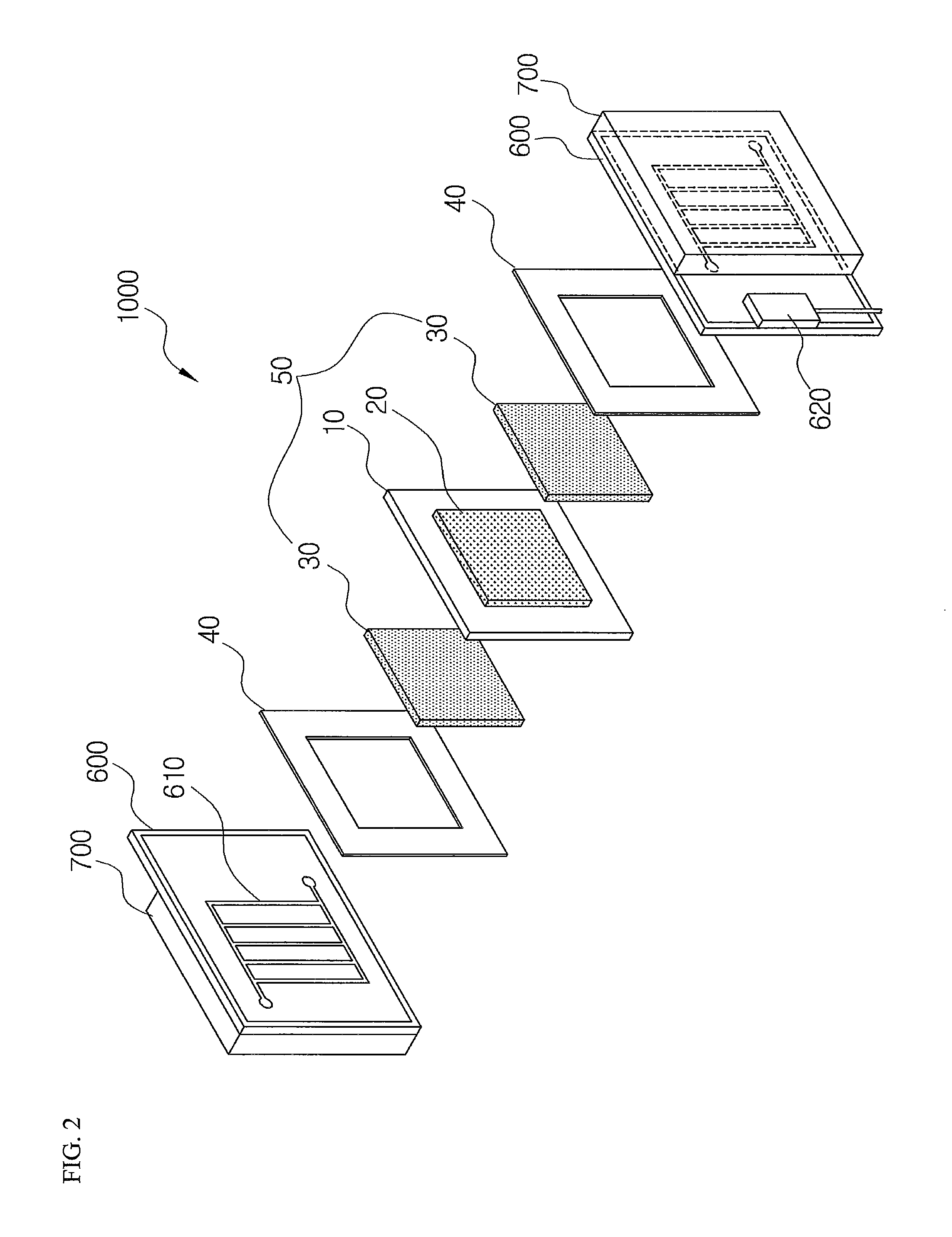
[0019]10: POLYMER ELECTROLYTE MEMBRANE[0020]20: CATALYST LAYER[0021]30: GAS DIFFUSION LAYER[0022]40: GASKET[0023]50: MEMBRANE ELECTRODE ASSEMBLY[0024]60: SEPARATOR[0025]600: CURRENT COLLECTOR PLATE[0026]610: CHANNEL[0027]700: TRANSPARENT PLATE[0028]800: FUEL DISTRIBUTION STRUCTURE[0029]900: LARGE AREA PEMFC VOLTAGE MEASURING UNIT[0030]910: REGION CELL MONITORING UNIT[0031]1000: VISUALIZATION APPARATUS FOR REGION CELL[0032]2000: VISUALIZATION APPARATUS FOR LARGE AREA PEMFC

BEST MODE

[0033]Hereinafter, a visualization apparatus for a PEMFC according to the present invention will be described in detail with reference to the accompanying drawings.

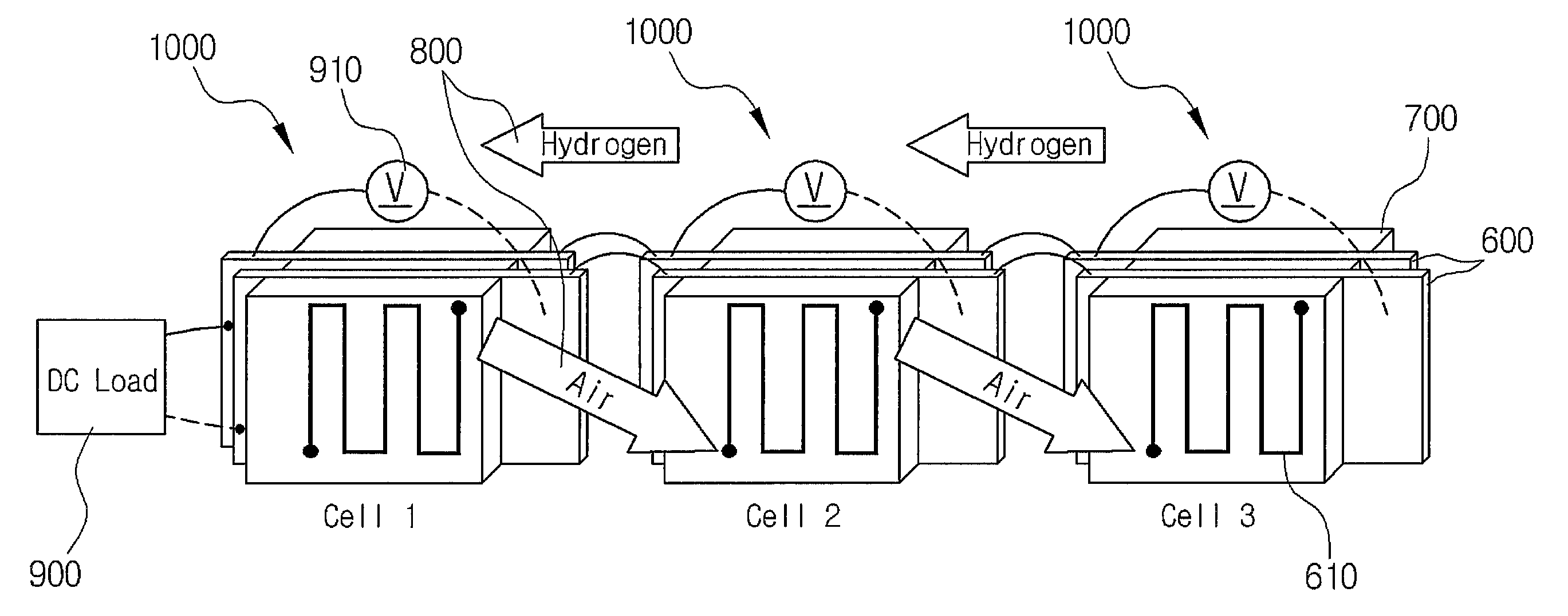
[0034]FIG. 2 is a shape of a visualization apparatus for a region cell. FIG. 3 shows an example of dividing a large area PEMFC into a region cell and FIG. 4 is a configuration diagram of a visualization apparatus for a large area PEMFC according to the present invention.

[0035]As shown in FIG. 2, unlike a real PEMFC, a general visualization appara...


PUM

PropertyMeasurementUnit
operating temperatureaaaaaaaaaa
thicknessaaaaaaaaaa
areaaaaaaaaaaa

Abstract

Provided is a visualization apparatus for a PEMFC using a transparent window. More particularly, provided is a visualization apparatus for a large are PEMFC including: a plurality of visualization apparatuses for region cells including current collector plates each provided on both sides of a membrane electrode assembly of a PEMFC and formed with channels through which reaction gas and products flow and a transparent provided on the outer surface of the current collector plate. Further, provided is a visualization apparatus for a large area PEMFC electrically connecting the current collector plates of the visualization apparatus for region cells to each other in parallel.

Description

TECHNICAL FIELD[0001]The present invention relates to a visualization apparatus for a large area PEMFC using a transparent window, and more particularly, to a visualization apparatus for a large area PEMFC capable of having conditions approximating a real PEMFC by implementing a single large area PEMFC having a large reaction area by electrically connecting a plurality of visualization apparatuses for region cells having a small unit reaction area in parallel and connecting them to each other in series in distributing fuel.BACKGROUND ART[0002]As environmental regulations of automobile markets are increasingly tightened, the world's carmakers have tried to develop environment-friendly and high-efficient cars. It is expected that the fuel-cell car will emerge as the center focus of an automobile market in the future because it is environmentally friendly in that it only discharges water while having high efficiency. As a result, many carmakers have continued to develop a fuel-cell car...

Claims


Application Information

Patent Timeline
Patent Type & Authority Patents(United States)
IPC IPC(8): H01M2/38H01M8/04H01M8/10H01M2/08H01M2/02H01M2/40H01M8/24H01M50/77
CPCH01M8/04305Y02E60/50H01M8/02H01M8/10G01R31/36
Inventor BAE, JOONGMYEONLEE, DONGRYUL
Owner KOREA ADVANCED INST OF SCI & TECH
Why Eureka
Try Eureka