
Power generation cell for fuel battery

Inactive Publication Date: 2011-06-30
TOYOTA SHATAI KK
View PDF4 Cites 5 Cited by
  • Summary
  • Abstract
  • Description
  • Claims
  • Application Information

AI Technical Summary

Benefits of technology

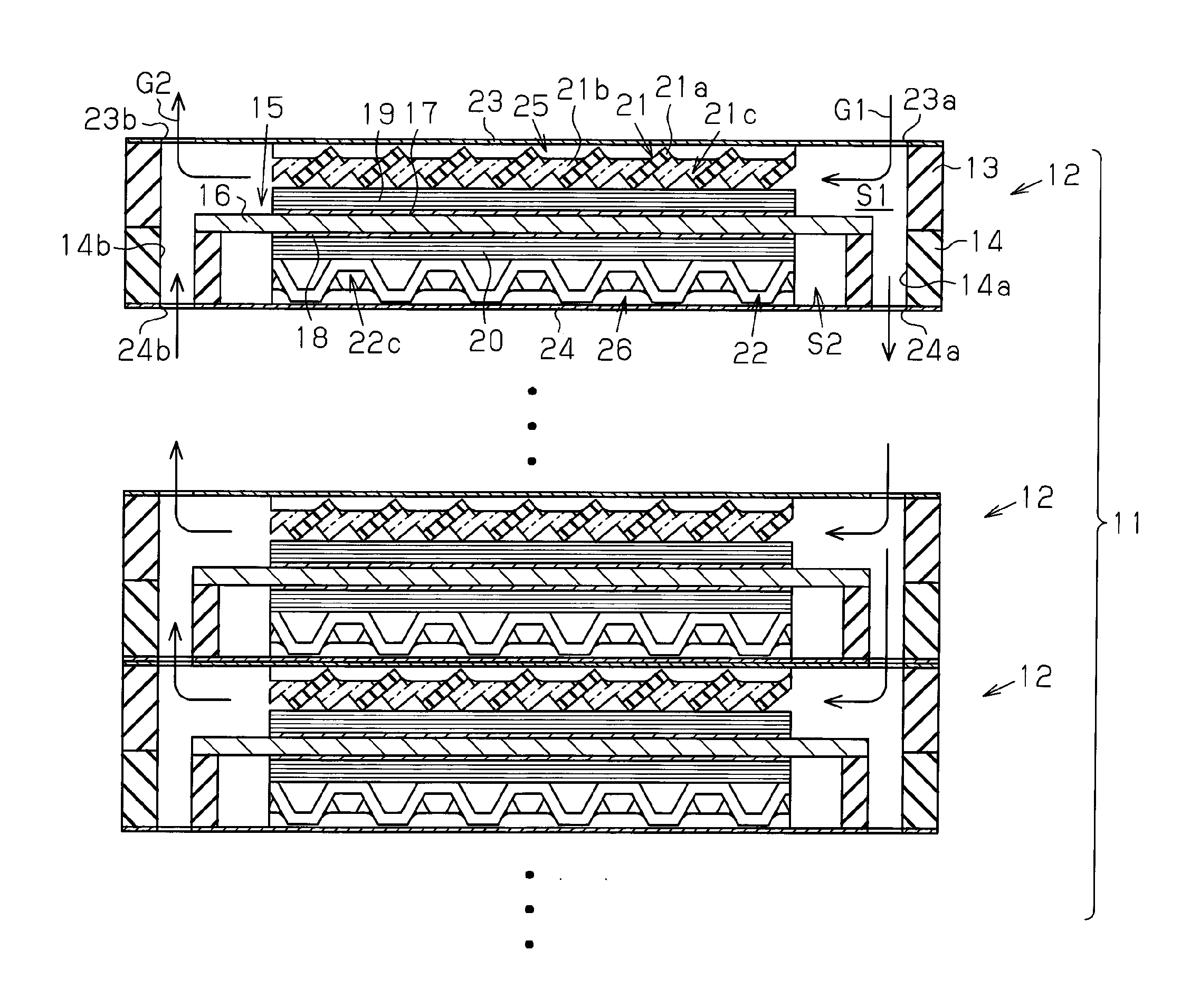
[0010]The present invention is directed to a power generation cell for a fuel battery that improves durability, voltage stability, and power generation efficiency.
[0012]In this structure, when generation water, which is generated by the power generation action of the power generation cell, and humidification water, which is supplied by a humidifier, condense and form water drops that collect on the wall surface of the gas flow path in the gas flow path formation body, the water drops are absorbed by the capillary shaped water passage water guide layer. The water absorbed by the water passage of the water guide layer is forced to the downstream side of the gas flow by the fuel gas or oxidation gas flowing through the gas flow path. As a result, water drops are eliminated from the gas flow path of the gas flow path formation body, and deterioration of the electrode assembly is prevented. Further, fuel gas and oxidation gas is smoothly supplied to the electrode assembly. Thus, the power generation cell performs power generation properly.

Problems solved by technology

This may vary the generated power voltage, cause flooding, and decrease voltage stability.
As a result, loss may be increased in a gas supplying device such as a compressor, and the power generation efficiency of the fuel battery may be decreased.

Method used


Image

  • Power generation cell for fuel battery
  • Power generation cell for fuel battery
  • Power generation cell for fuel battery

Examples


Embodiment Construction

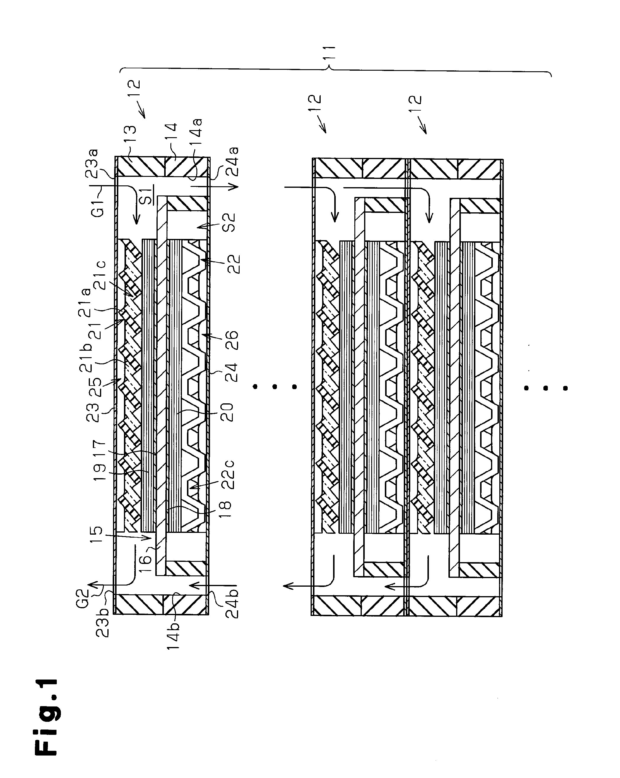
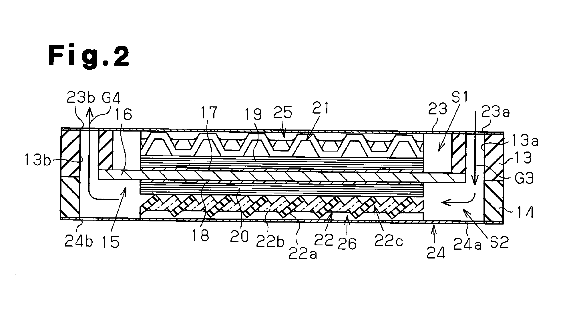
[0031]A fuel battery according to one embodiment of the present invention will now be discussed with reference to FIGS. 1 to 7.

[0032]As shown in FIGS. 1 and 3, a solid polymer fuel battery stack 11 is formed by stacking a plurality of power generation cells 12.

[0033]As shown in FIG. 1, a power generation cell 12 is formed to have the shape of a square frame. The power generation cell 12 includes first and second frames 13 and 14, which are formed from a synthetic rubber (or synthetic resin), and a membrane-electrode-assembly) MEA 15, which serves as an electrode assembly arranged between the two frames 13 and 14. The first and second frames 13 and 14 include a fuel gas passage opening S1 and an oxidation gas passage opening S2. Further, the power generation cell 12 includes a first gas flow path formation body 21, which is accommodated in the fuel gas passage opening S1, and a second gas flow path formation body 21, which is accommodated in the oxidation gas passage opening S2. The ...


PUM


Abstract

An electrolyte membrane 16 is arranged inside first and second frames 13 and 14. The electrolyte membrane 16 has a first surface, on which an anode side electrocatalytic layer 17 is superimposed, and a second surface, on which a cathode side electrocatalytic layer 18 is superimposed. The electrocatalytic layer 17 has a surface on which an anode side gas flow path formation body 21 including a gas flow path 21c for supplying fuel gas is superimposed. Further, the electrocatalytic layer 18 has a surface on which a cathode side gas flow path formation body 22 including a gas flow path 22c for supplying oxidation gas is superimposed. The first and second gas flow path formation bodies 21 and 22 have surfaces on which first and second separators 23 and 24 are superimposed, respectively.

Description

FIELD OF THE INVENTION[0001]The present invention relates to a fuel battery for a fuel battery system installed in, for example, an electric vehicle or the like.BACKGROUND OF THE INVENTION[0002]A fuel battery generally includes a cell stack, which is a stack of power generation cells. As shown in FIG. 11, a power generation cell 12 includes two frames 13 and 14, which are arranged one above the other, and an electrode assembly 15, which is arranged at a coupled portion of the frames 13 and 14. The electrode assembly 15 includes a solid electrolyte membrane (hereinafter referred to as an electrolyte membrane) 16, an anode side electrocatalytic layer 17, and a cathode side electrocatalytic layer 18. The electrolyte membrane 16 includes an outer rim held between the two frames 13 and 14. The electrolyte membrane 16 includes an upper surface on which the electrocatalytic layer 17 is superimposed. Further, the electrolyte membrane 16 includes a lower surface on which the electrocatalytic...

Claims


Application Information

Patent Timeline
IPC IPC(8): H01M8/04H01M8/10
CPCH01M8/0228H01M8/023H01M8/04171Y02T90/32H01M2250/20Y02E60/50H01M2008/1095Y02T90/40
Inventor KONDO, TAKASHI
Owner TOYOTA SHATAI KK
Learn More