Water jet propulsion watercraft

a watercraft and water jet technology, applied in waterborne vessels, marine propulsion, vessel construction, etc., can solve the problems of weak reverse drive force, low reverse drive speed, inadequate reverse drive force, etc., to achieve adequate reverse drive direction propulsive force, facilitate facilitating the effect of hull turning

Active Publication Date: 2011-06-30
YAMAHA MOTOR CO LTD
View PDF9 Cites 9 Cited by
  • Summary
  • Abstract
  • Description
  • Claims
  • Application Information

AI Technical Summary

Benefits of technology

On the other hand, when the pair of deflectors are rotated in the same direction from the straight drive positions to either the right or the left, the water flow jetting direction of one of the reverse drive jet ports approaches a direction parallel or substantially parallel to the hull centerline. A rearward direction propulsive force that is parallel or substantially parallel to the hull centerline can thereby be increased. That is, an adequate reverse drive direction propulsive force can be secured when performing reverse drive while turning. Further, the water flow jetting direction of the other reverse drive jet port includes a component that gives rise to a propulsive force that moves the stern to the rotation direction of the deflector. The turning of the hull can thereby be facilitated. Moreover, the water flow jetting direction of the other reverse dr

Problems solved by technology

Thus, when straight reverse drive is performed, the propulsive force is weak and a reverse drive speed is low.
The same applies in the case of reverse drive in the right direction, and the propulsive force in the reverse drive direction is inadequate.
Thus, in actuality, although the j et propulsion watercraft can be turned at

Method used


Image

  • Water jet propulsion watercraft
  • Water jet propulsion watercraft
  • Water jet propulsion watercraft

Examples


first preferred embodiment

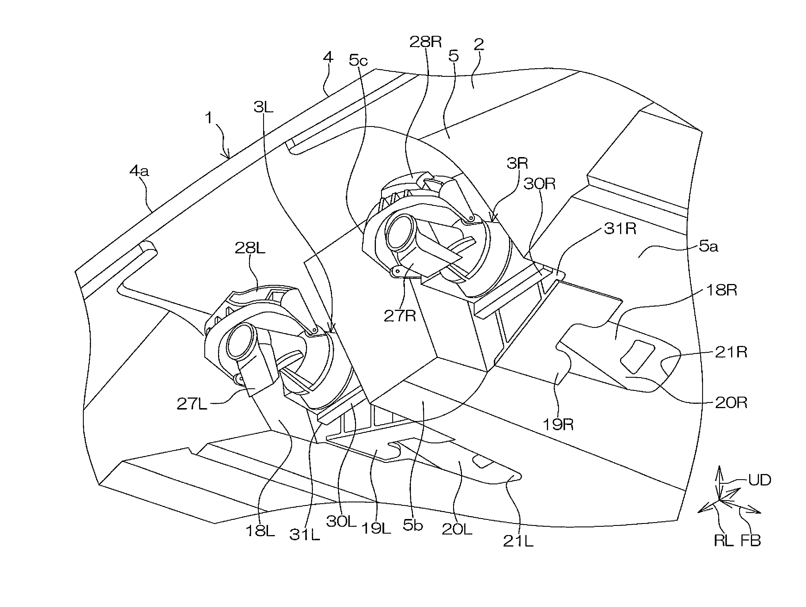
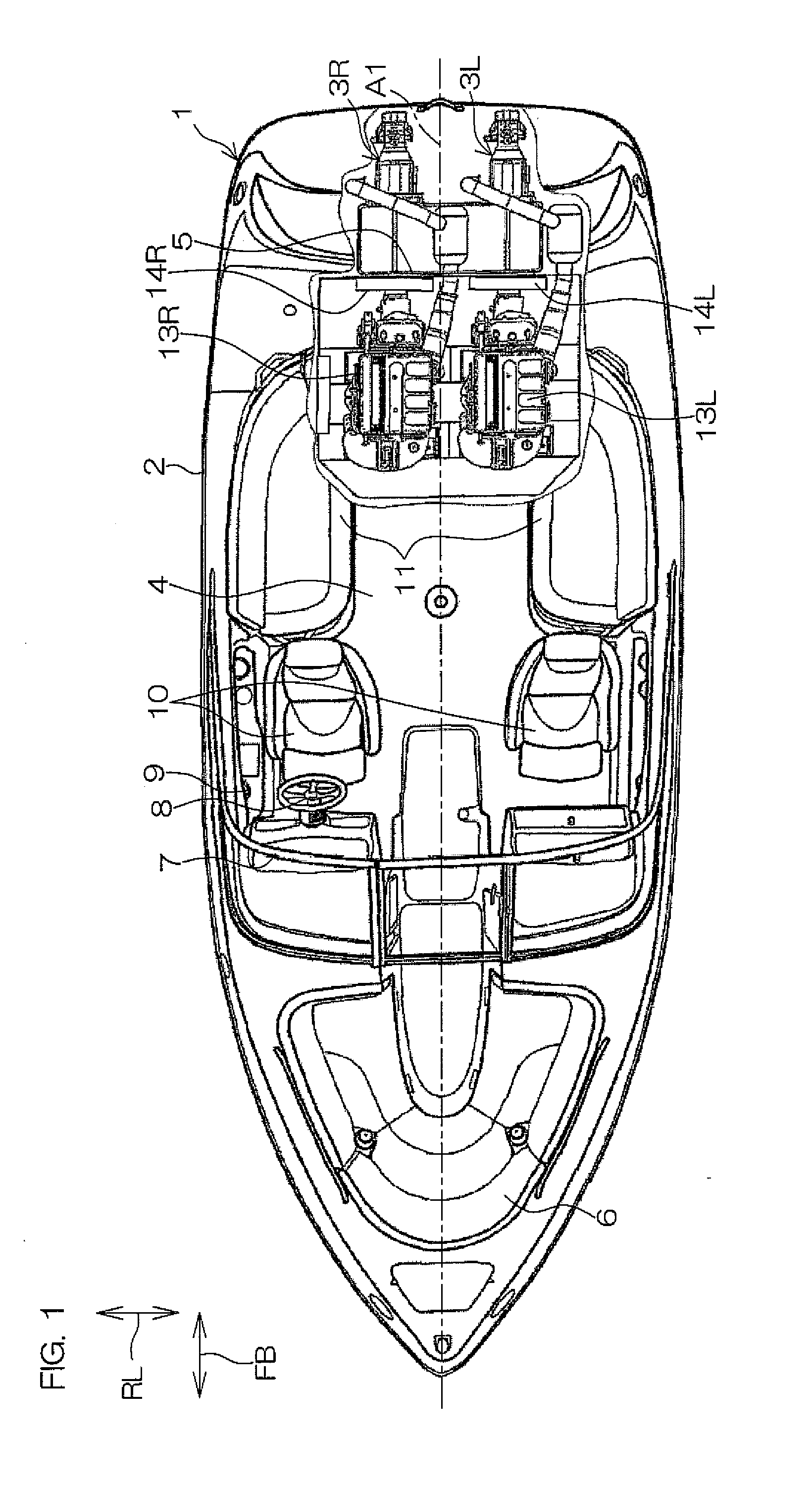
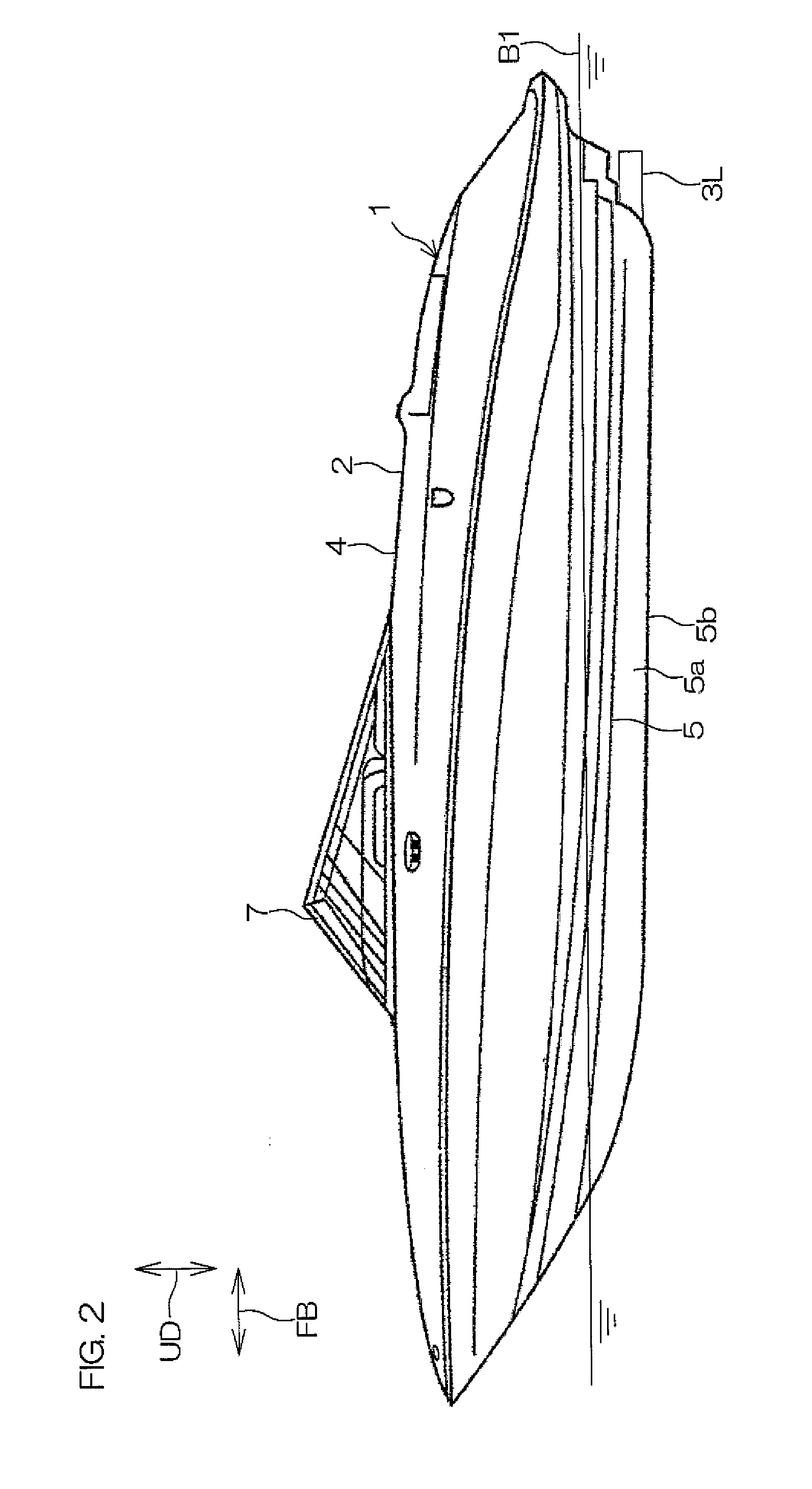
FIG. 1 is a plan view of a general arrangement of a water jet propulsion watercraft 1 according to a first preferred embodiment of the present invention with a portion of a hull being broken away to show an arrangement of an interior of the hull. The water jet propulsion watercraft 1 is used for traveling on the water on a lake and at sea, etc. The water jet propulsion watercraft 1 preferably includes a hull 2, and a pair of right and left jet propulsion devices 3L and 3R attached to the hull 2 and arranged in a right / left symmetrical manner across a hull centerline A1. The hull centerline A1 is a straight line passing through centers of a stem and a stern in plan view.

The hull 2 extends long in a front / rear direction FB of the hull 2 and has a predetermined width in a right / left direction RL of the hull 2. In the following description, the front / rear direction FB of the hull 2 shall be referred to simply as the “front / rear direction FB.” The right / left direction RL of the hull 2 sh...

second preferred embodiment

FIG. 23 is a bottom view of principal portions of a water jet propulsion watercraft 101 according to a second preferred embodiment of the present invention. In the following description, arrangements, actions, and effects that differ from those of the first preferred embodiment shall be described. Arrangements that are the same as those of the first preferred embodiment shall be provided with the same symbols, and description of the arrangements, actions, and effects thereof shall be omitted.

A principal point of difference of the water jet propulsion watercraft 101 according to the second preferred embodiment of the present invention with respect to the water jet propulsion watercraft 1 according to the first preferred embodiment of the present invention lies in the arrangement of reverse drive jet ports 153R and 153L included in the deflectors 27R and 27L. Specifically, water flow jetting directions of the reverse drive jet ports 153R and 153L of the respective deflectors 27R and 2...


PUM


Abstract

A water jet propulsion watercraft includes a pair of jet propulsion devices arranged right and left of a hull centerline. Each jet propulsion device includes a jetting unit arranged to jet water, a deflector supported on the hull and arranged to rotate to right and left, the deflector including a forward drive jet port and a reverse drive jet port. Each jet propulsion device includes a bucket arranged to change between a forward drive position and a reverse drive position. The bucket includes a reflecting surface arranged to reflect the water jetted from the forward drive jet port when the bucket is at the reverse drive position, and an auxiliary nozzle including an entrance opened to the reflecting surface and arranged to jet water introduced into the entrance along a hull right/left direction. The entrance of the auxiliary nozzle is spaced away from the forward drive jet port in the hull right/left direction and does not oppose the forward drive jet port in a state where the bucket is arranged at the reverse drive position and the deflector is arranged at the straight drive position.

Description

BACKGROUND OF THE INVENTION1. Field of the InventionThe present invention relates to a water jet propulsion watercraft.2. Description of the Related ArtA water jet propulsion watercraft travels on water by a propulsive force generated by a jet propulsion device attached to a hull. The jet propulsion device sucks in and jets water to generate the propulsive force.For example, a water jet propulsion watercraft according to a prior art disclosed in U.S. Pat. No. 6,875,064 B2 includes a pair of right and left jet propulsion devices disposed at a rear end of a hull. In this prior art, the pair of right and left jet propulsion devices respectively include stator nozzles 301R and 301L, steering nozzles 302R and 302L, and reverse gates 303R and 303L as shown in FIG. 28. Each of the stator nozzles 301R and 301L discharges a water flow, generated by rotation of an impeller, toward a rear of the hull. The steering nozzles 302R and 302L are rotatable to right and left about pivot axes 304R and ...

Claims


Application Information

Patent Timeline
IPC IPC(8): B63H11/11
CPCB63H11/11B63H11/08
Inventor OTA, NOBUHARUSATO, HIDEYOSHI
Owner YAMAHA MOTOR CO LTD
Why Eureka
Try Eureka