Shift manipulating device for an automatic transmission

a technology of automatic transmission and manipulating device, which is applied in the direction of mechanical control device, manual control with single controlling member, instruments, etc., can solve the problems of large-sized shift lever device as a whol

Inactive Publication Date: 2005-08-02
NILES PARTS CO LTD
View PDF10 Cites 32 Cited by
  • Summary
  • Abstract
  • Description
  • Claims
  • Application Information

AI Technical Summary

Benefits of technology

[0021]The invention also provides a shift manipulating device for an automatic transmission, comprising a path which is formed on an upper cover of a control switch device and permits a shift lever of the automatic transmission to be inserted therethrough to thereby restrict a direction of manipulation of the shift lever wherein the shift lever has a lower end thereof disposed within a casing which is mounted on the upper cover, and a buzzer is arranged in the casing.

Problems solved by technology

Therefore, there is caused a problem that the shift lever device is made large-sized as a whole.
Since the shift lever device is arranged in a manner to prevent movements of the actuator via the substantially L-shaped linkage and the lock plate, there is caused a problem that the linkage and the lock plate occupy an interior of the device to make the shift lever device large-sized as a whole.

Method used


Image

  • Shift manipulating device for an automatic transmission
  • Shift manipulating device for an automatic transmission
  • Shift manipulating device for an automatic transmission

Examples


Embodiment Construction

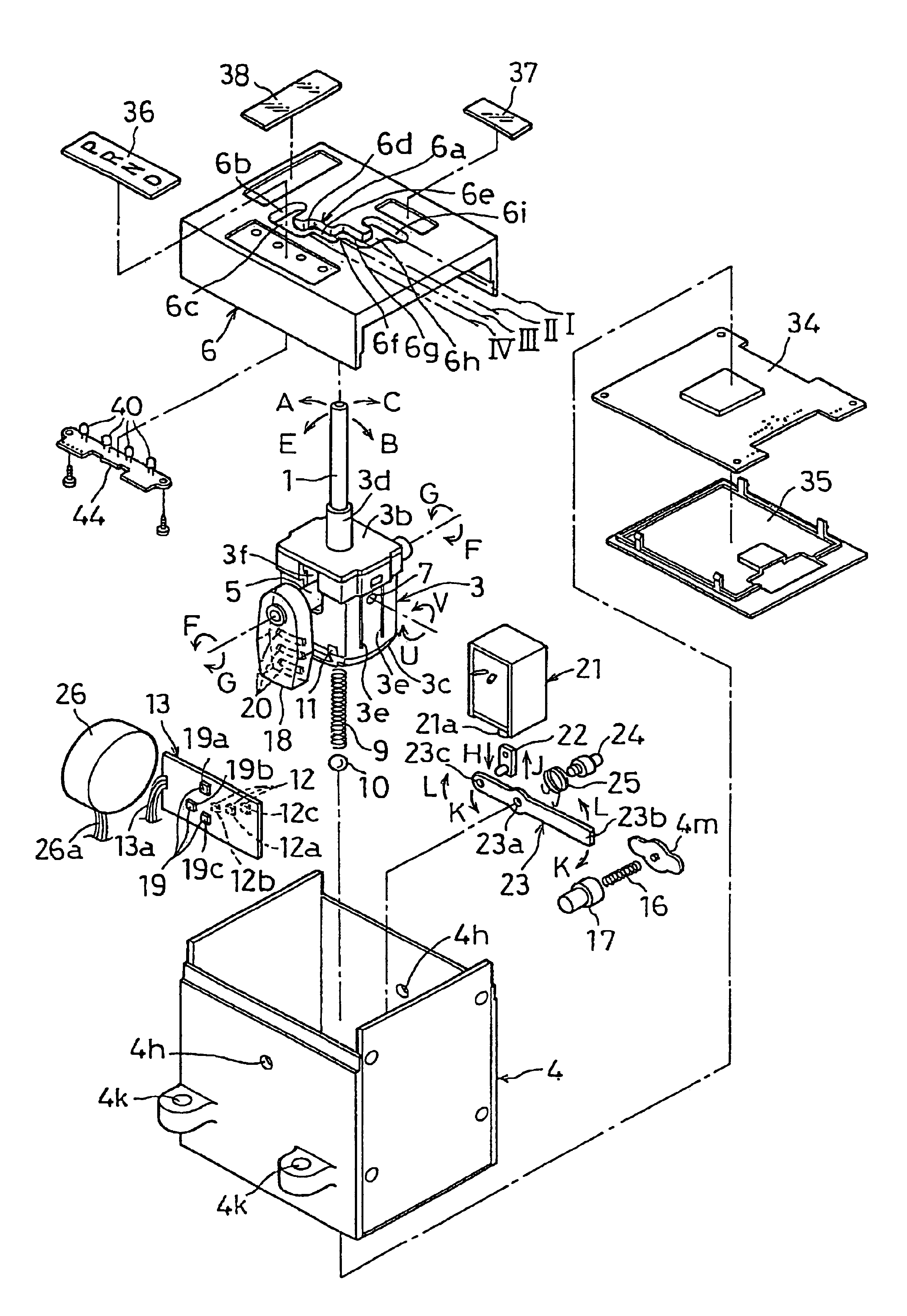
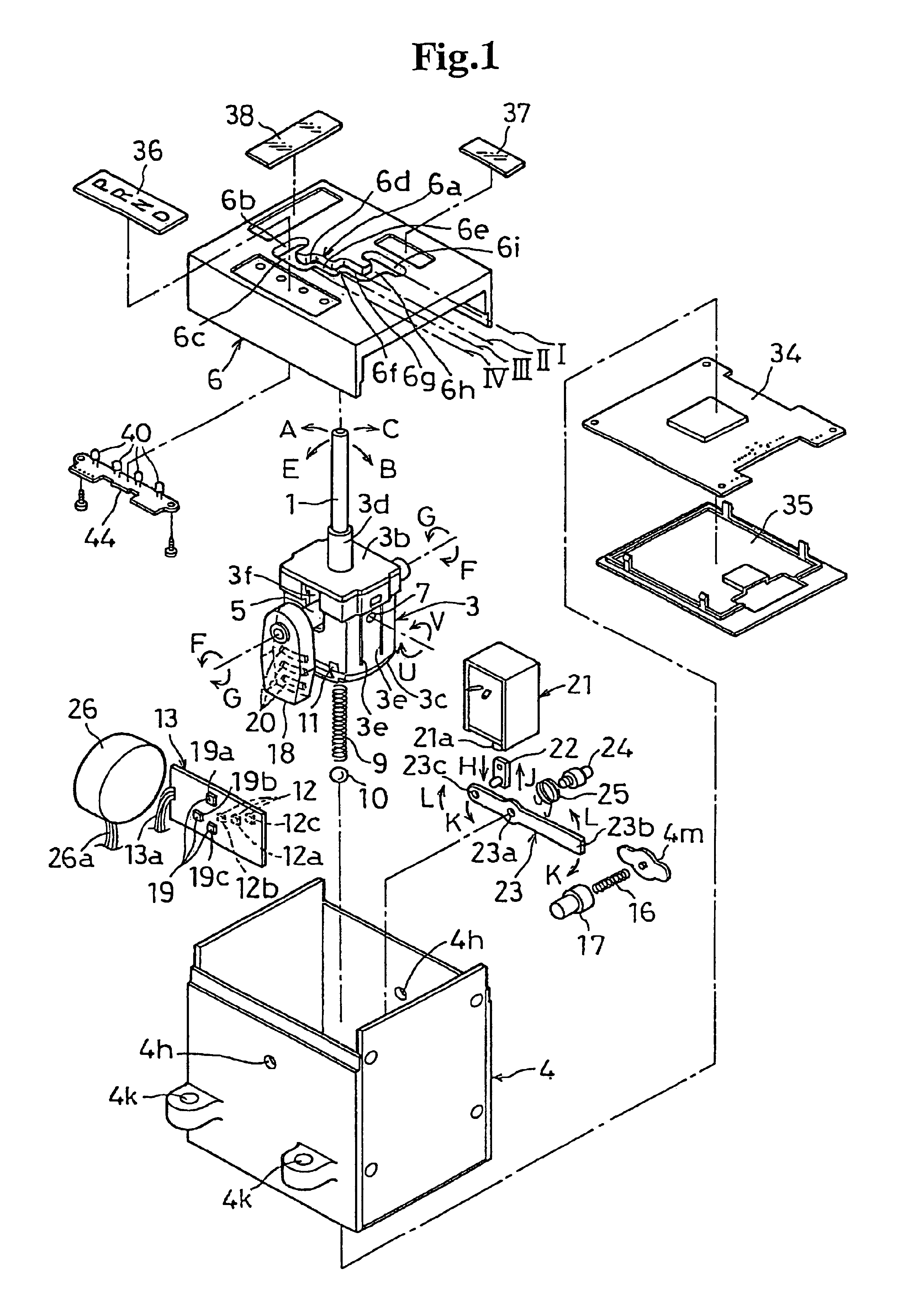
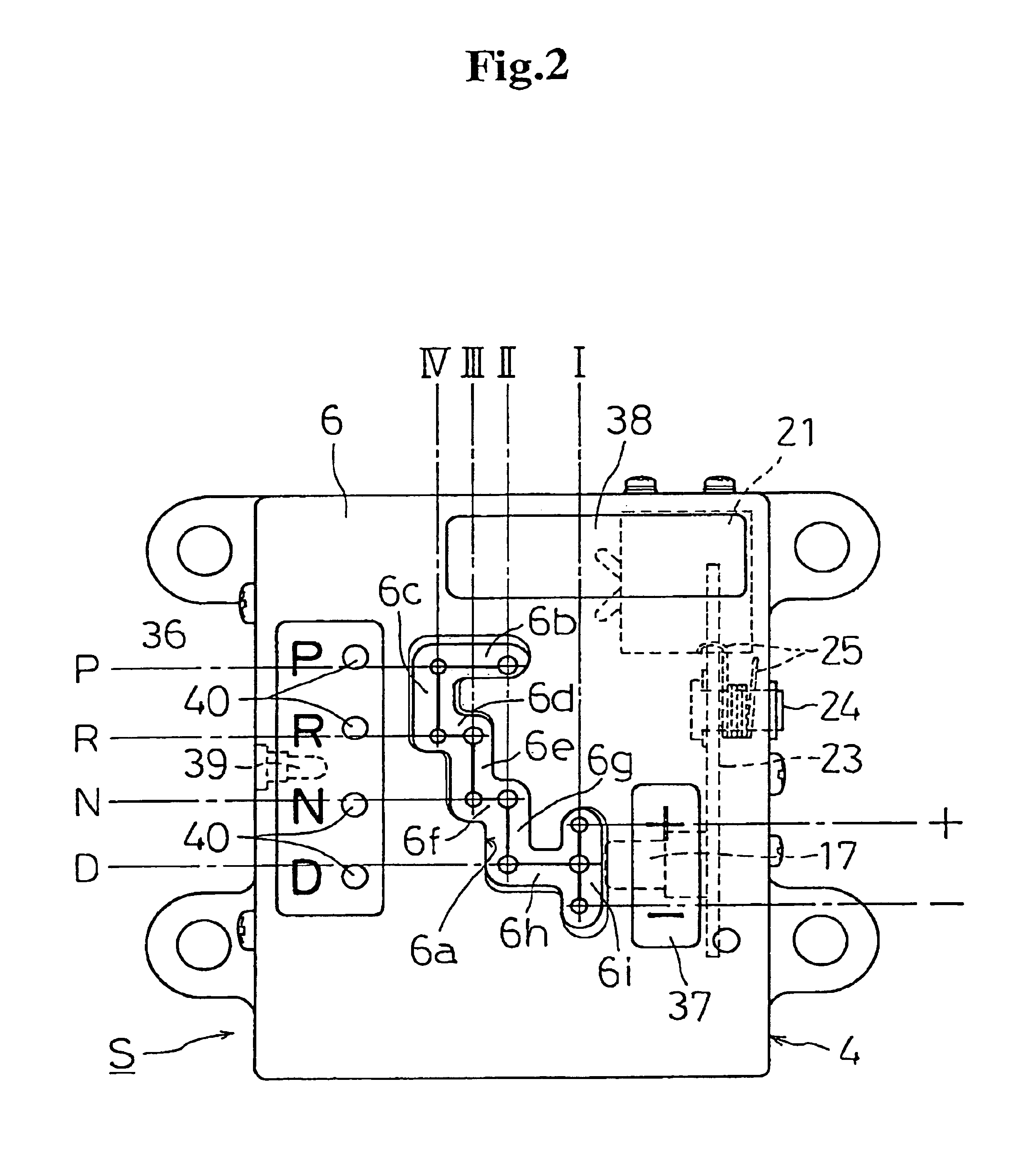
[0033]Embodiments of the invention will be described below with reference to FIGS. 1 to 11. In FIGS. 1, 2, 3 and 4, the reference numeral 1 denotes a shift lever loaded on an automobile with an automatic transmission, the shift lever serving for shift manipulation to a desired running position from respective positions such as running, stoppage, parking or the like. The shift lever 1 is made from, for example, a metallic rod-shaped pipe, and fix a knob 2 at its upper end and a holder 3 at its lower end, the lever being swingably supported on a first shaft 5 and a second shaft 7 disposed in a casing 4.

[0034]The upper end of the shift lever 1 is inserted through a path 6a formed through an upper cover 6 to swingably protrude outside the casing 4 to be guided by the path 6a for swinging operation. The lower end of the shift lever 1 is inserted into an upper portion 3b of the holder 3 to be fixed thereto by means of screws 8 to swing together with the holer 3.

[0035]Also, the shift lever...


PUM


Abstract

A shift manipulating device for an automatic transmission includes a shift lever of an automatic transmission device and a path formed on an upper cover of a control switch device. The path includes manipulating positions arranged in at least P range, R range, N range and D range in this order, and on three lines, that is, second line, third line and fourth line in right and left directions. The P range is arranged in a first path on the second line and at an end of the path, the R range is arranged in a second path on the fourth line of the first path, the N range is in a third path on the second line of the second path, and the D range is in a fourth path on the second line.
Thus the number of parts and man-hour for assembling are reduced.

Description

BACKGROUND OF THE INVENTION[0001]1. Field of the Invention[0002]The invention relates to a shift manipulating device for an automatic transmission, which is usable for a shift lever for shift to a desired operating position among respective operating positions such as running, stoppage, parking or the like in an automobile loaded with an automatic transmission.[0003]2. Description of the Related Art[0004]For example, Japanese Patent Laid-Open No. 192852 / 1999 discloses an invention of a shift manipulating device of this type for an automatic transmission in the prior art. The shift manipulating device is actuated by the swinging manipulation of a shift lever, and is provided with an A / T switch, which serves to transmit to a transmission side an electric signal corresponding to a desired operating position, and an electrically driven type actuator for drivingly separating an engaging pin, which inhibits movements of a shift lever, from an engaging groove on a detent plate.[0005]The le...

Claims


Application Information

Patent Timeline
Patent Type & Authority Patents(United States)
IPC IPC(8): F16H59/02F16H59/10B60K20/02F16H61/26
CPCF16H59/0204F16H59/105F16H61/24F16H2059/0239Y10T74/20098Y10T74/20201Y10T74/20122Y10T74/20159Y10T74/20018
Inventor FUJINUMA, TAKAO
Owner NILES PARTS CO LTD
Why Eureka
Try Eureka