Refrigerant evaporator

a technology of refrigerant evaporator and evaporator body, which is applied in the direction of indirect heat exchangers, domestic cooling devices, lighting and heating devices, etc., can solve the problems of increasing the distance of the refrigerant flow passage, increasing the pressure loss, and difficult to improve the performance of the refrigerant evaporator, so as to reduce the pressure loss, improve performance, and reduce the corner portion

Active Publication Date: 2005-10-27
DENSO CORP
View PDF10 Cites 33 Cited by
  • Summary
  • Abstract
  • Description
  • Claims
  • Application Information

AI Technical Summary

Benefits of technology

[0006] The present invention was accomplished in view of the problems inherent in the above prior art and its object is to provide a refrigerant evaporator having a simplified tank structure yet constituting the front-and-rear right-and-left cross path and producing less pressure loss on the refrigerant side.
[0009] According to the present invention, increased sectional areas of the flow passages are obtained at the ends of the tank portion in the right-and-left direction (refrigerant flow corner portions) by simple means making it possible to decrease the pressure loss on the refrigerant side in the tank and to improve performance.
[0012] According to the present invention, further, the flow of the refrigerant has decreased corner portions and a short flow passage in the tanks, making it possible to decrease the pressure loss on the refrigerant side in the tanks and to improve performance.

Problems solved by technology

This, however, results in an increase in the distance of the refrigerant flow passages and, hence, in an increase in the pressure loss making it difficult to improve performance of the refrigerant evaporator.
The problem, however, has been how to realize the heat exchanger having the front-and-rear right-and-left cross path in a simple constitution that facilitates the mass production.

Method used


Image

  • Refrigerant evaporator
  • Refrigerant evaporator
  • Refrigerant evaporator

Examples


first embodiment

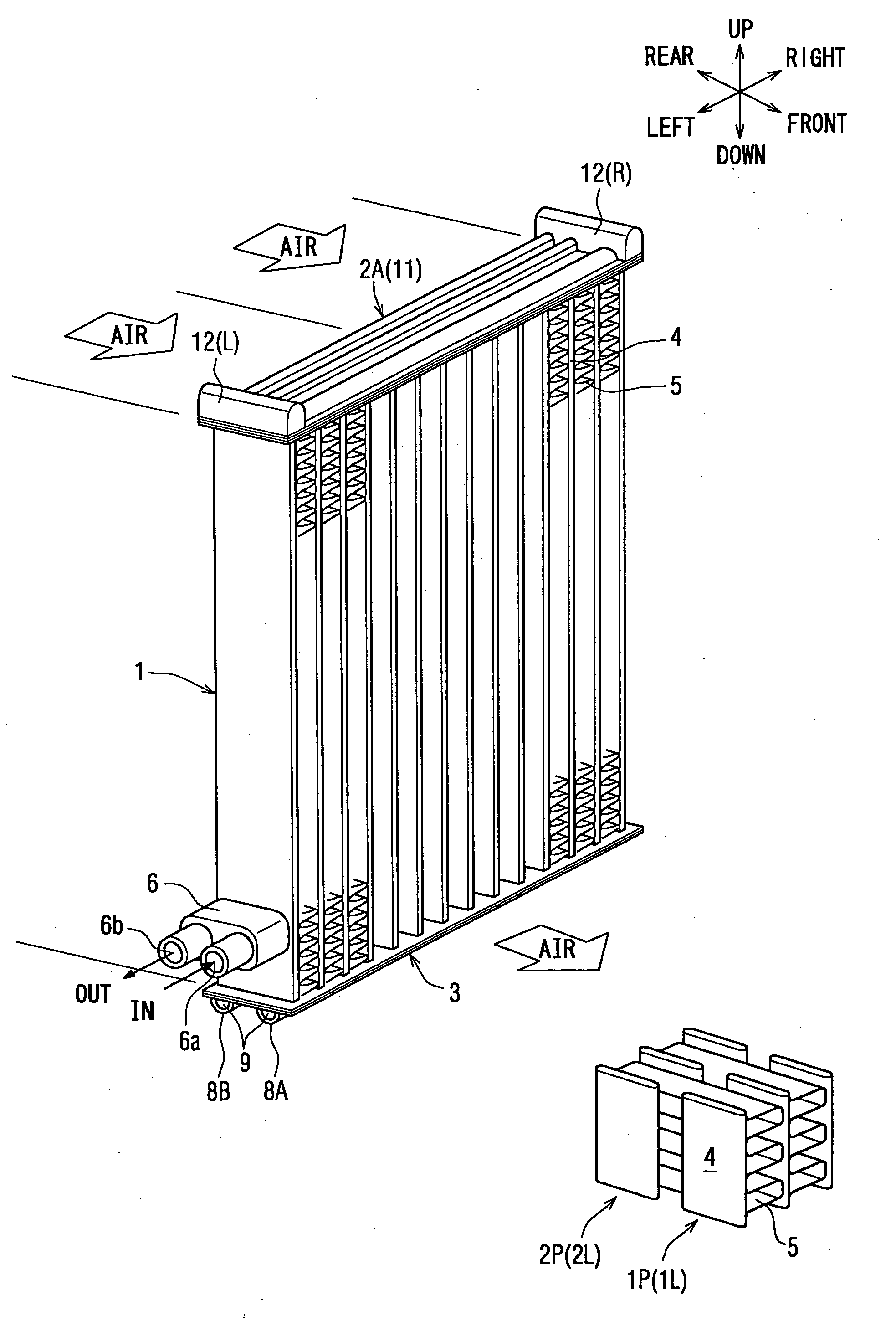
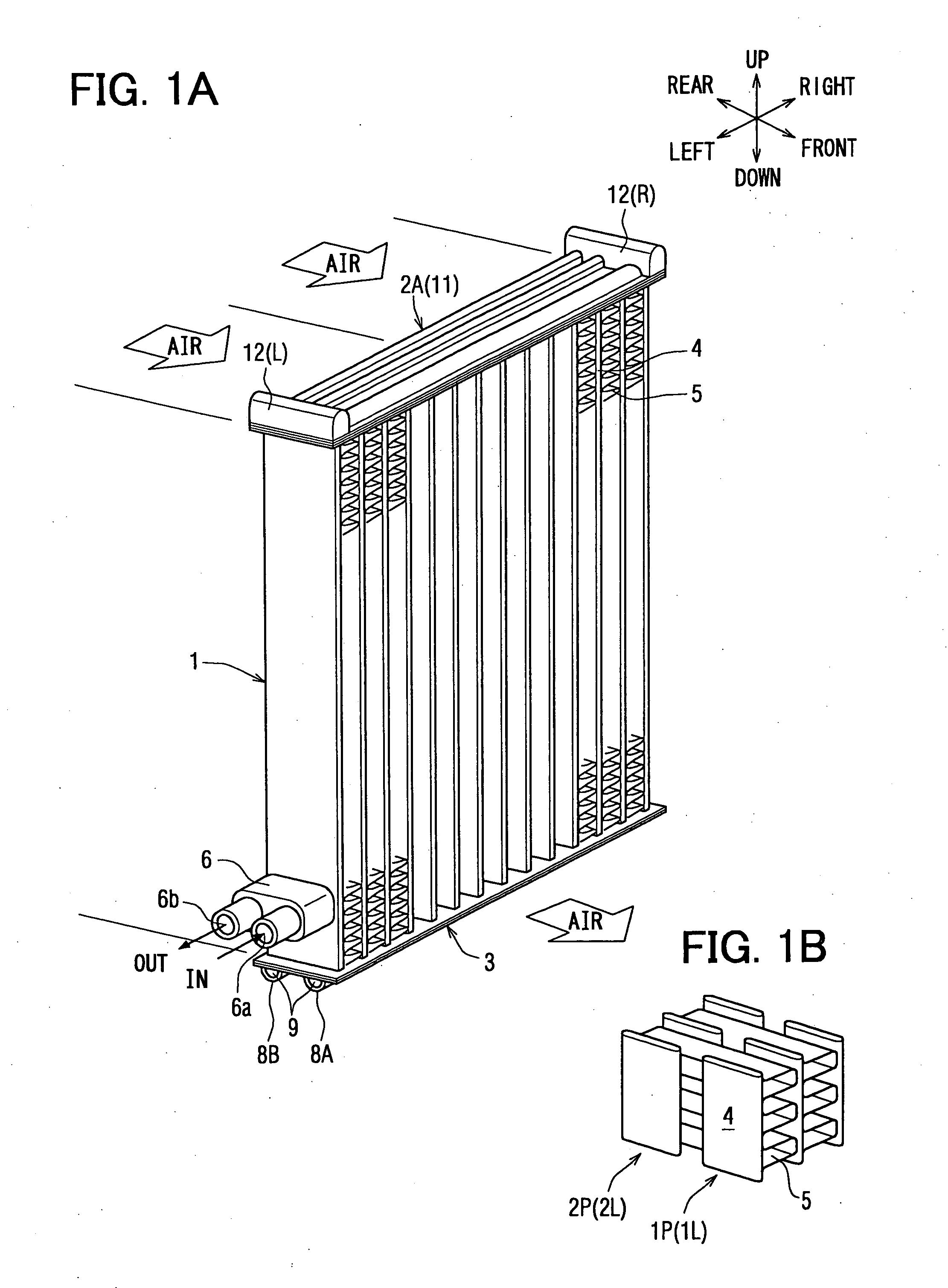
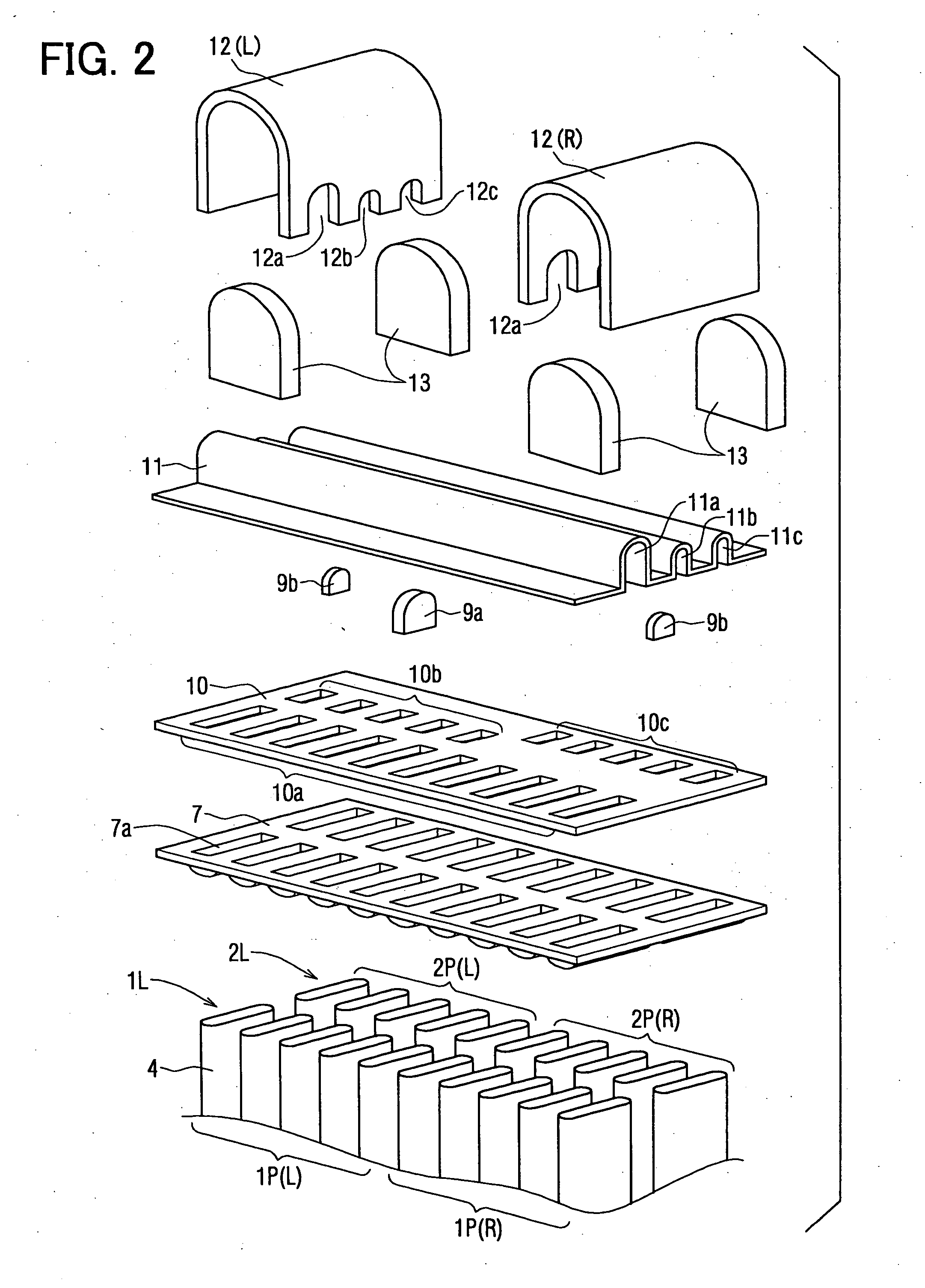
[0042] An embodiment of the invention will now be described in detail with reference to the drawings. FIG. 1 is a perspective view of a refrigerant evaporator 1 according to a first embodiment of the invention, and FIG. 2 is a perspective view illustrating, in a disassembled manner, the constitution of an upper tank portion in the refrigerant evaporator of FIG. 1A. In this specification, the front-and-rear direction is such that the leeward side is the front and the windward side is the rear, and the right-and-left direction stands for the direction of the width of the core in which the tubes (flat tubes) 4 are arranged on an orthogonal plane facing the direction of the airflow.

[0043] This embodiment is applied to the front-and-rear U-turn evaporator of the constitution in which the path stretches in the direction of whole width, and the description deals with a case where the refrigerant evaporator 1 of the invention is applied to the supercritical refrigerating cycle that operate...

embodiment 1

Another Embodiment 1

[0058]FIG. 5A is a partial perspective view illustrating another embodiment 1 of the refrigerant evaporator 1 of FIG. 1, and FIG. 5B is a partial sectional view of the tank portion 11b vertically cut at the center thereof in FIG. 5A. The communication is blocked by using the side surface portion of the side tank 12 at a portion where the tank portions 11b, 11c are not to be communicated with the interior of the side tank 12. More concretely, FIG. 5A illustrates a portion where the tank portion 11a is communicated with the tank portion 11c through the side tank 12 at the left end of the upper tank 2A and is not communicated with the tank portion 11b.

[0059] For this purpose, a cut-away portion k1 is formed in the tank portion 11b at an end in the longitudinal direction, and the side tank 12 is not provided with an opening 12b but has a shape 12b′ corresponding to the cut-away portion k1. The outer side surface of the side tank 12 is brought into contact with the e...

embodiment 2

Another Embodiment 2

[0060]FIG. 6A is a partial perspective view illustrating another embodiment 2 of the refrigerant evaporator 1 of FIG. 1, and FIG. 6B is a partial sectional view of the tank portion 11b vertically cut at the center thereof in FIG. 6A. A cut portion k2 is formed instead of the cut-away portion k1 at the same portion as that of the above embodiment 1, and one side surface of the side tank 12 is inserted in the cut portion k2 to block the communication. This also makes it possible to omit the separators 9b which are the constituent parts and, hence, to suppress the cost. Further, the cut portion k2 works to more reliably position the side tank 12 in the direction of width of the core portion.


PUM


Abstract

A refrigerant evaporator includes a tank constituted by a tank portion and a header plate. The tank portion includes refrigerant collecting portions for guiding the refrigerant passed through a first path to the ends of the tank in the right-and-left direction and refrigerant distributing portions for guiding the refrigerant to the tubes forming a second pass. The header plate has refrigerant collecting / distributing space for the tubes. Side tanks are arranged to cover open portions at the ends of the tank in the right-and-left direction, and to spatially connect the flow passages. Separators are provided at portions where the flow passages are to be spatially blocked to constitute a front-and-rear right-and-left cross path. An increased sectional area of flow passages is obtained at the refrigerant flow corner portions relying upon a simple constitution, to decrease the pressure loss on the refrigerant side in the tank and to enhance performance.

Description

CROSS REFERENCE TO RELATED APPLICATION [0001] This application is based on Japanese Patent Application No. 2004-114569 filed on Apr. 8, 2004, the disclosure of which is incorporated herein by reference. FIELD OF THE INVENTION [0002] This invention relates to a refrigerant evaporator for evaporating the refrigerant in a refrigerating cycle, which can be favorably used, for example, for an air conditioning system for vehicles. The refrigerant evaporator can be further used as an outdoor heat exchanger in a heat pump cycle. BACKGROUND OF THE INVENTION [0003] In recent years, study has been forwarded to control the airflow rates independently for the driver's seat and the assistant's seat to meet the requirements of the users of the vehicles. The above requirements have been heretofore been satisfied by controlling the airflow rate through the refrigerant evaporator independently on the right side and on the left side in the direction of core width. When the airflow rate is to be indepe...

Claims


Application Information

Patent Timeline
Patent Type & Authority Applications(United States)
IPC IPC(8): F28F9/02F25B39/02F25D23/12F28D1/053
CPCF25B39/02F28D1/05391F28F9/0278F28F9/0204F28F9/0221F28D2021/0085
Inventor KATOH, YOSHIKIHASEGAWA, ETSUOKAWAKUBO, MASAAKI
Owner DENSO CORP
Why Eureka
Try Eureka