Exhaust gas treatment apparatus

a technology of exhaust gas treatment and exhaust gas, which is applied in the direction of emission prevention, separation processes, instruments, etc., can solve the problems of difficult to maintain the active temperature range of the catalyst in the catalyst, the actual operating temperature of the coal-burning boiler is lower than the design temperature, and the ammonium sulfate may clog the exhaust gas passage, so as to improve the efficiency and lifespan of the denitrification catalyst, reduce the emission of nitrogen oxides, and improve the efficiency of the deni

Active Publication Date: 2015-07-23
GSCO
View PDF2 Cites 8 Cited by
  • Summary
  • Abstract
  • Description
  • Claims
  • Application Information

AI Technical Summary

Benefits of technology

[0025]As set forth above, according to embodiments of the invention, high temperature exhaust gas can be supplied to a nitrogen oxide decreasing device through a passage bypassing a heat exchanger, so as to increase the temperature of exhaust gas making contact with a denitrification catalyst to the active temperature range of the denitrification catalyst. Therefore, the efficiency of the denitrification catalyst can be improved, and the emission of nitrogen oxides can be reduced.
[0026]In addition, according to the embodiments of the invention, high temperature exhaust gas supplied through a bypass can be mixed rapidly and uniformly with relatively low temperature exhaust gas flowing in a main discharge passage to maintain the temperature of exhaust gas to be uniform in the nitrogen oxide decreasing device and thus to uniformly expose the denitrification catalyst to exhaust gas. Therefore, nitrogen oxides can be uniformly decomposed over the entire region of the denitrification catalyst for increasing the efficiency and lifespan of the denitrification catalyst.
[0027]According to the embodiments, in addition to decreasing the emission of nitrogen oxides, the denitrification catalyst can be regenerated even in the case that the denitrification catalyst is poisoned. That is, the denitrification catalyst can easily be maintained and used for a long period of time with constant catalysis efficiency.
[0028]In addition, according to the embodiments, a variable exhaust regulator can have a simple structure, and thus parts such as dampers necessary for controlling flows of exhaust gas in the bypass or the main discharge passage can also have simple structures. Therefore, the exhaust gas treatment apparatus can easily be manufactured, installed, and maintained. Furthermore, the exhaust gas treatment apparatus can be operated with less pressure loss.
[0029]In addition, according to the embodiments, the direction and amount of exhaust gas passing through the variable exhaust regulator can be adjusted so as to rapidly make the exhaust gas uniform and control the temperature and temperature distribution of the exhaust gas at the nitrogen oxide decreasing device.
[0030]In addition, according to the embodiments, it takes less time to make exhaust gas uniform before the exhaust gas is supplied to the nitrogen oxide decreasing device. That is, an exhaust gas discharge passage can be shortened.

Problems solved by technology

In some cases, however, the actual operating temperatures of coal-burning boilers are lower than designed temperatures thereof due to the low caloric power of recently-produced coal.
Particularly, when operating a boiler in a low-load condition, it may be difficult to maintain the catalyst active temperature range therein.
In addition, ammonium sulfate may clog exhaust gas passages of the SCR device and a heat exchanger such as an air preheater to increase pressure loss within a boiler.
However, such a catalyst regeneration method requires relatively expensive chemicals, and it may require a significant amount of money to treat waste water.
Furthermore, since a boiler can't be operated while a catalyst is regenerated, a great deal of loss may be caused.
However, the method disclosed is for powder catalysts and thus is not suitable for catalysts having a honeycomb, a flat plate, or a wave shapes that are most commonly used in nitrogen oxide decreasing devices (such as SCR devices) of boilers.
Furthermore, in the related art, during boiler operations, ammonia has to be continuously supplied to an SCR device, and there is a limit on increasing the temperature of the SCR to 300° C. or higher.
Therefore, the efficiency of catalyst regeneration may be low.
However, the technique disclosed for regenerating a catalyst using high temperature exhaust gas supplied through a bypass may cause non-uniform temperature distribution in the SCR device, and the temperature of the SCR device may not be maintained within a proper temperature range if exhaust gas flows backwards in the bypass or if a sufficient amount of exhaust gas is not supplied through the bypass.
However, such a gas distributor may increase the interior pressure of a boiler to lower the thermal efficiency thereof, and the gas distributor may be damaged by constant exposure to high temperature exhaust gas.

Method used


Image

  • Exhaust gas treatment apparatus
  • Exhaust gas treatment apparatus
  • Exhaust gas treatment apparatus

Examples


Embodiment Construction

[0044]Exemplary embodiments of the present invention will now be described in detail with reference to the accompanying drawings. The present invention may, however, be embodied in many different forms and should not be construed as being limited to the embodiments set forth herein. In the drawings, the sizes and shapes of elements may be exaggerated for clarity, and like reference numerals denote like elements.

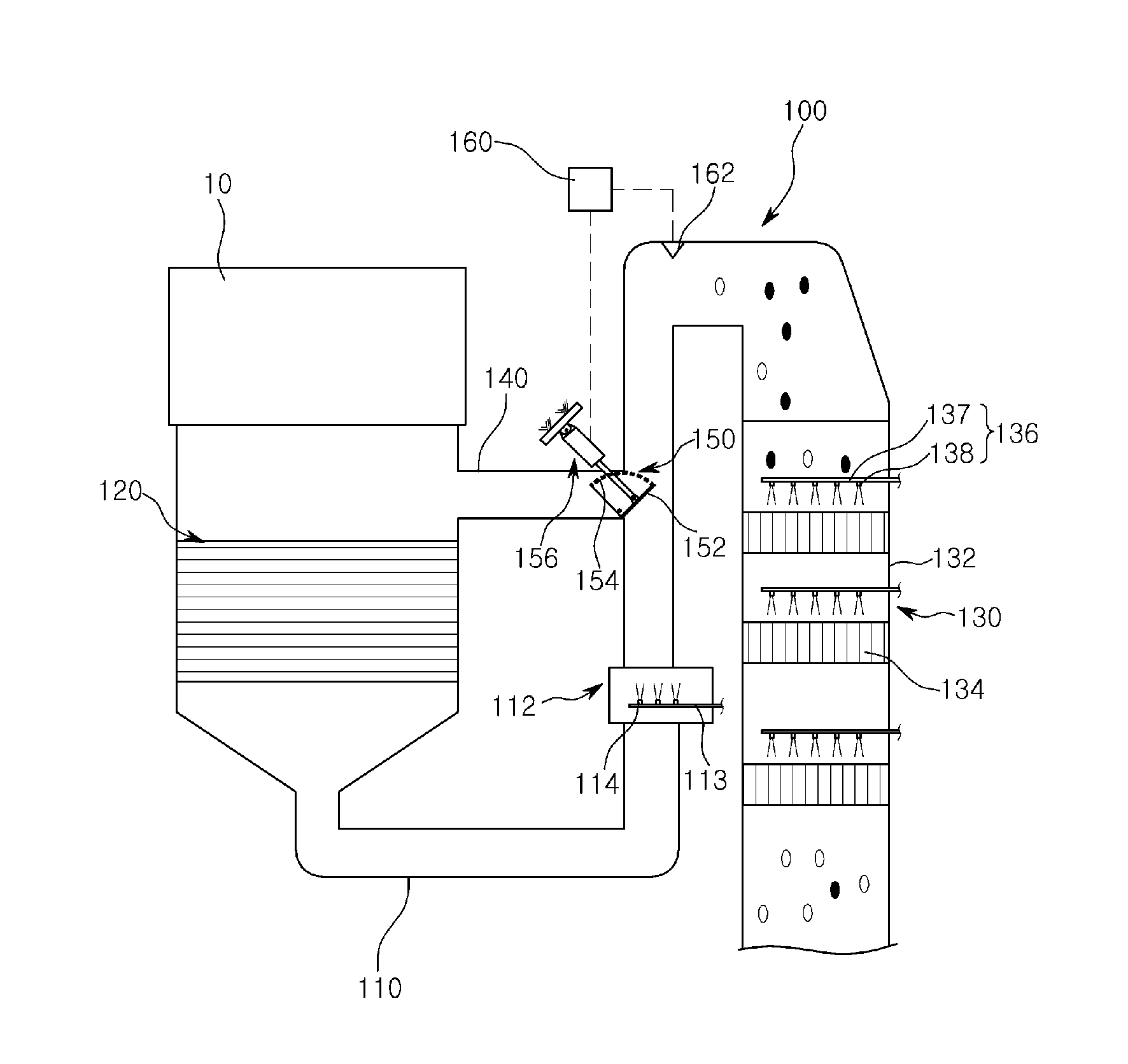
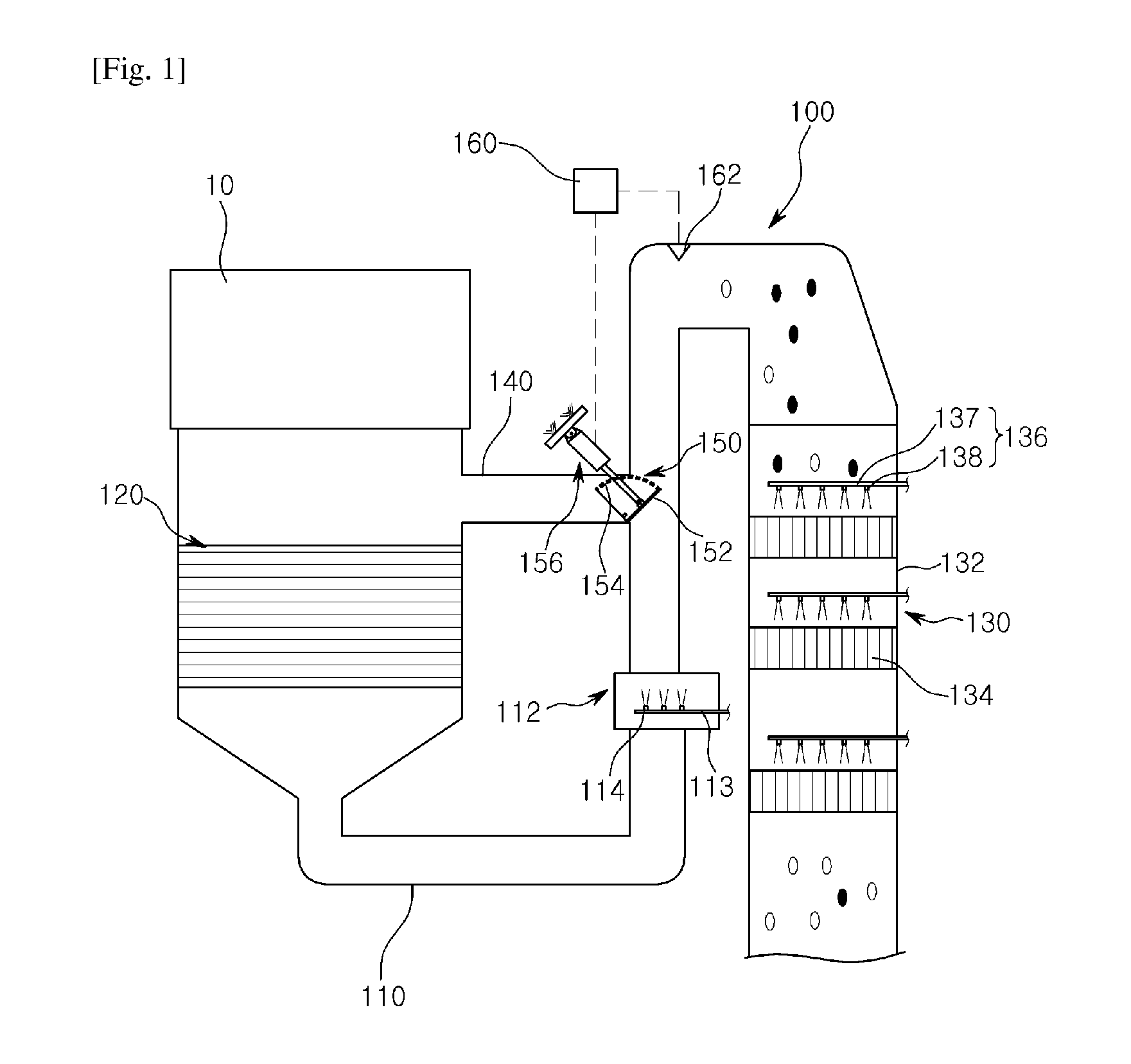
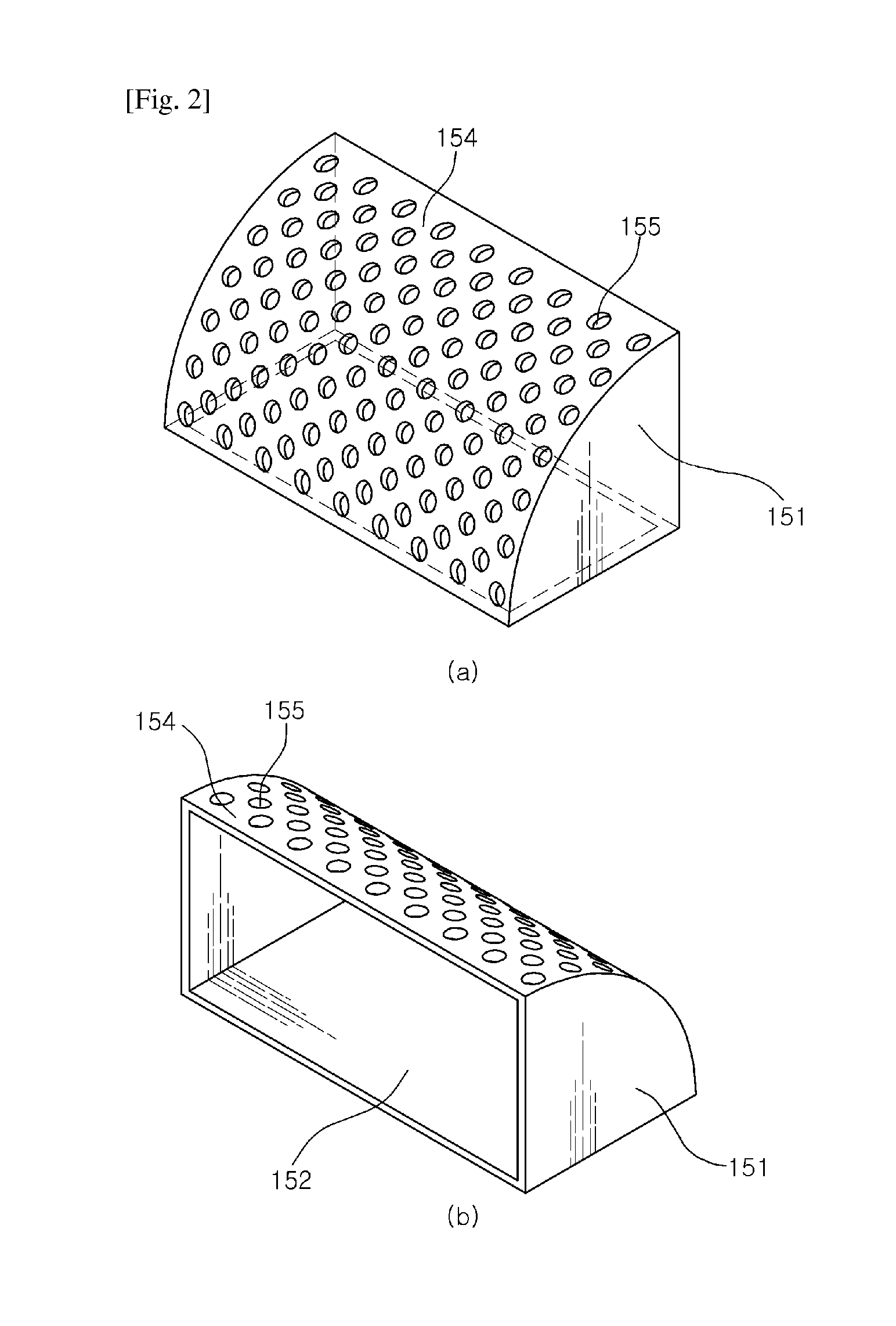
[0045]FIG. 1 is a schematic view illustrating an exhaust gas treatment apparatus 100 according to an embodiment of the invention, and FIG. 2 is a partial perspective view illustrating a variable exhaust regulator 150 of the exhaust gas treatment apparatus 100 according to the embodiment of the invention. FIG. 3 is a view for explaining how the variable exhaust regulator 150 is operated in the exhaust gas treatment apparatus 100 according to the embodiment of the invention.

[0046]Referring to FIGS. 1 to 3, according to the embodiment of the invention, the exhaust gas treatment ...


PUM


Abstract

There is provided an exhaust gas treatment apparatus. The exhaust gas treatment apparatus includes: a main discharge passage through which exhaust gas of combustion equipment is discharged; an heat exchanger between the combustion equipment and the main discharge passage; a nitrogen oxide decreasing device connected to the main discharge passage to decrease nitrogen oxides of exhaust gas; a bypass connected from the combustion equipment to the main discharge passage as a passage bypassing the heat exchanger to supply high temperature exhaust gas from the combustion equipment to the nitrogen oxide decreasing device; and a variable exhaust regulator disposed between the bypass and the main discharge passage to vary the amount of relatively high temperature exhaust gas flowing in the bypass and the amount of exhaust gas flowing in the main discharge passage in a correlated manner.

Description

TECHNICAL FIELD[0001]The present invention relates to an exhaust gas treatment apparatus for reducing pollutants contained within exhaust gas generated during combustion, and more particularly, to an exhaust gas treatment apparatus for reducing pollutant emission by increasing the temperature of exhaust gas to the active or regeneration temperature range of a catalytic device.BACKGROUND ART[0002]In general, types of combustion equipment such as boilers using coal, oil, gas, or other combustible materials, generate exhaust gasses during combustion. Pollutants such as nitrogen oxides (NOx) may be contained in exhaust gas generated by such equipment, and thus it is necessary to develop techniques for protecting the atmosphere from pollutants such as nitrogen oxides (NOx).[0003]Such nitrogen oxides can be reduced by controlling combustion (a pretreatment method) or treating exhaust gas (a post-treatment method).[0004]Most post-treatment methods employ a selective catalyst reduction (SCR...

Claims


Application Information

Patent Timeline
Patent Type & Authority Applications(United States)
IPC IPC(8): B01D53/94F01N3/08F01N3/02
CPCB01D53/9431F01N3/0814F01N3/0205F23J13/00F23J15/04F23J2215/10F23J2219/40F23L11/00F23J11/00
Inventor CHO, BUK-RYONGKIM, DAE-WOOPARK, HA-KUE
Owner GSCO
Why Eureka
Try Eureka