Refrigerant evaporator
a technology of refrigerant evaporator and evaporator body, which is applied in the direction of indirect heat exchangers, domestic cooling devices, lighting and heating devices, etc., can solve the problems of increasing the distance of the refrigerant flow passage, increasing the pressure loss, and difficult to improve the performance of the refrigerant evaporator, so as to reduce the pressure loss, improve performance, and reduce the corner portion
- Summary
- Abstract
- Description
- Claims
- Application Information
AI Technical Summary
Benefits of technology
Problems solved by technology
Method used
Image
Examples
first embodiment
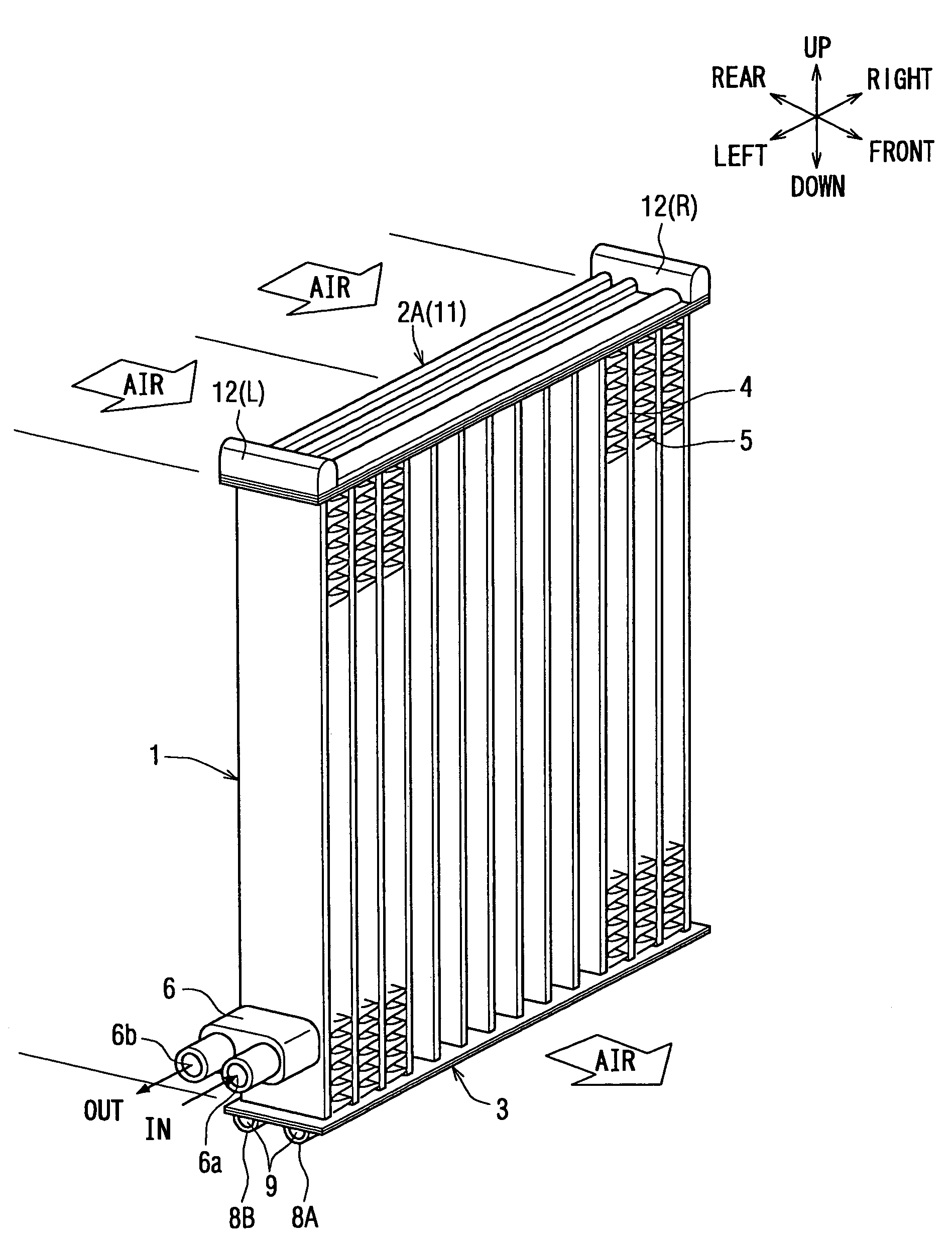
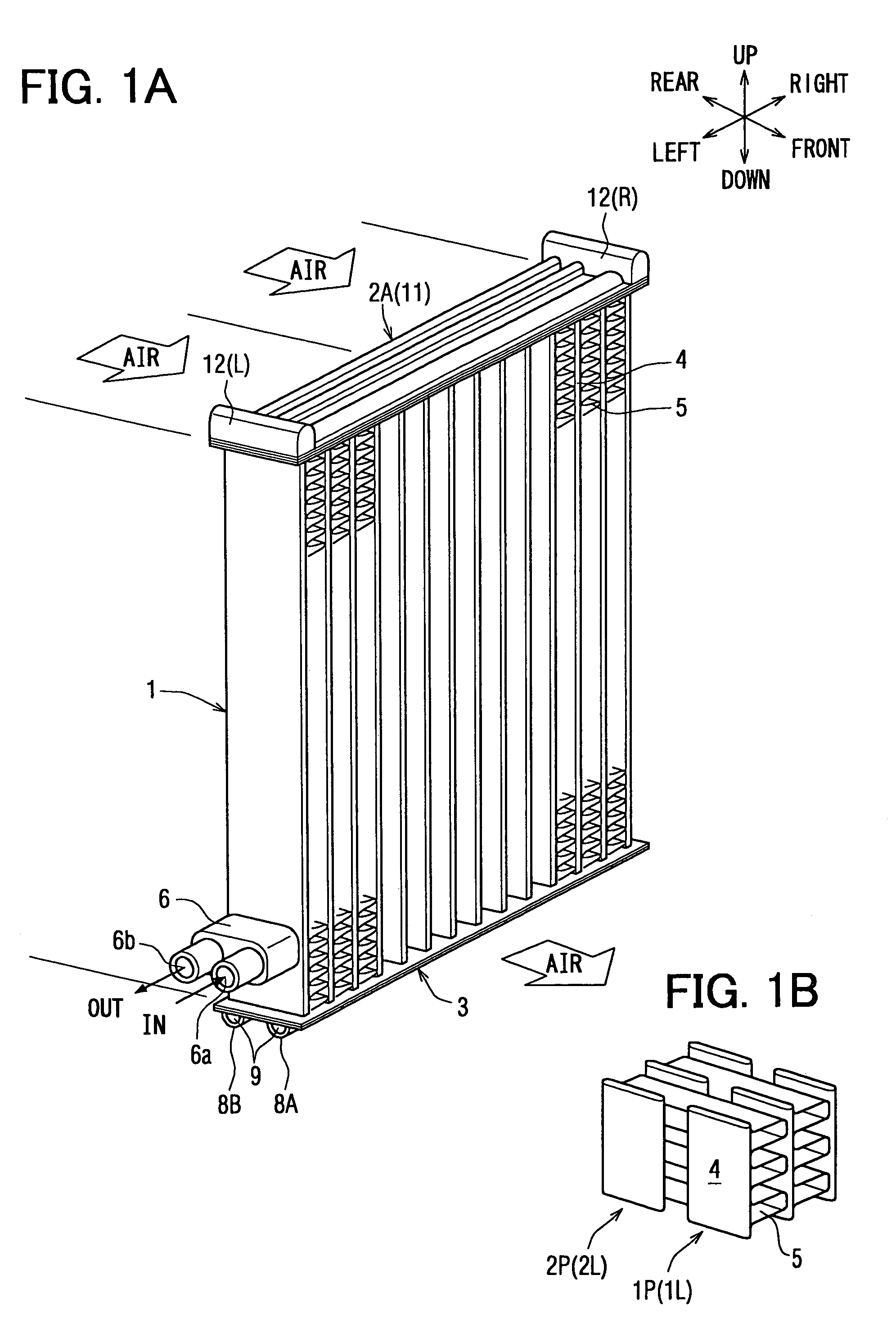
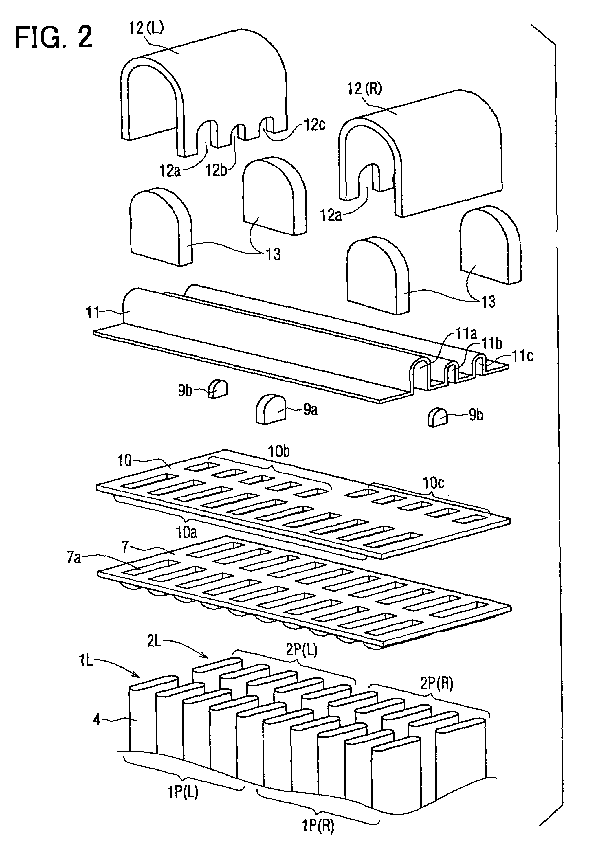
[0042]An embodiment of the invention will now be described in detail with reference to the drawings. FIG. 1 is a perspective view of a refrigerant evaporator 1 according to a first embodiment of the invention, and FIG. 2 is a perspective view illustrating, in a disassembled manner, the constitution of an upper tank portion in the refrigerant evaporator of FIG. 1A. In this specification, the front-and-rear direction is such that the leeward side is the front and the windward side is the rear, and the right-and-left direction stands for the direction of the width of the core in which the tubes (flat tubes) 4 are arranged on an orthogonal plane facing the direction of the airflow.
[0043]This embodiment is applied to the front-and-rear U-turn evaporator of the constitution in which the path stretches in the direction of whole width, and the description deals with a case where the refrigerant evaporator 1 of the invention is applied to the supercritical refrigerating cycle that operates w...
embodiment 1
Another Embodiment 1
[0058]FIG. 5A is a partial perspective view illustrating another embodiment 1 of the refrigerant evaporator 1 of FIG. 1, and FIG. 5B is a partial sectional view of the tank portion 11b vertically cut at the center thereof in FIG. 5A. The communication is blocked by using the side surface portion of the side tank 12 at a portion where the tank portions 11b, 11c are not to be communicated with the interior of the side tank 12. More concretely, FIG. 5A illustrates a portion where the tank portion 11a is communicated with the tank portion 11c through the side tank 12 at the left end of the upper tank 2A and is not communicated with the tank portion 11b.
[0059]For this purpose, a cut-away portion k1 is formed in the tank portion 11b at an end in the longitudinal direction, and the side tank 12 is not provided with an opening 12b but has a shape 12b′ corresponding to the cut-away portion k1. The outer side surface of the side tank 12 is brought into contact with the en...
embodiment 2
Another Embodiment 2
[0060]FIG. 6A is a partial perspective view illustrating another embodiment 2 of the refrigerant evaporator 1 of FIG. 1, and FIG. 6B is a partial sectional view of the tank portion 11b vertically cut at the center thereof in FIG. 6A. A cut portion k2 is formed instead of the cut-away portion k1 at the same portion as that of the above embodiment 1, and one side surface of the side tank 12 is inserted in the cut portion k2 to block the communication. This also makes it possible to omit the separators 9b which are the constituent parts and, hence, to suppress the cost. Further, the cut portion k2 works to more reliably position the side tank 12 in the direction of width of the core portion.
PUM
 Abstract
Description
Claims
Application Information
 - R&D
- Intellectual Property
- Life Sciences
- Materials
- Tech Scout
- Unparalleled Data Quality
- Higher Quality Content
- 60% Fewer Hallucinations
Browse by: Latest US Patents, China's latest patents, Technical Efficacy Thesaurus, Application Domain, Technology Topic, Popular Technical Reports.
© 2025 PatSnap. All rights reserved.Legal|Privacy policy|Modern Slavery Act Transparency Statement|Sitemap|About US| Contact US: help@patsnap.com


