
Muscle Training Apparatus and Belt for Muscle Training

a training apparatus and muscle technology, applied in the field of muscle training apparatus and belt for muscle training, can solve the problems of increasing the burden on muscles and joints, slow-twitch muscle fibers are limited in their potential for growth, and fast-twitch muscle fibers require a significant amount of exercises, so as to prevent stretch

Active Publication Date: 2011-06-30
KAATSU JAPAN
View PDF9 Cites 19 Cited by
  • Summary
  • Abstract
  • Description
  • Claims
  • Application Information

AI Technical Summary

Benefits of technology

[0039]This belt has the opening into which the one end of the band-shaped member can be inserted, between the one end of the band-shaped member and the other end thereof. In addition, this belt is adapted to be placed on the target compressed site of the user while applying predetermined tension to said band-shaped member by means of pulling said one end of said band-shaped member and said other end thereof in opposite directions, with said target compressed site of the user being placed in a loop made of a part of said band-shaped member extending from said opening to an appropriate position on the side of said one end, the loop being generated by means of passing said one end of said band-shaped member through said opening. Final placement of the belt is made by maintaining the shape of said band-shaped member to which the predetermined tension is being applied, by means of said fastening means. With this belt, the band-shaped member can be tightened by means of pulling both ends of the band-shaped member in the opposite directions. Accordingly, with this belt, the user can pull the one end of the band-shaped member with his or her one hand while holding the other end with his or her other hand. Likewise, the user can pull the other end with his other hand while holding the one end with his or her one hand. Unlike the conventional belts, it is possible to avoid sliding rotation of the whole band-shaped member about the target compressed site when it is tightened.
[0047]When the belt having the inflatable pneumatic bag is placed on the target compressed site of the user, as in the case of the aforementioned belt, the target compressed site of the user is placed in a loop made of a part of the band-shaped member extending from the opening to an appropriate position on the side of the one end, the loop being generated by means of passing the one end of the band-shaped member through the opening. Under such a state, the one end and the other end of the band-shaped member are pulled in the opposite directions. Even when the inflatable pneumatic bag is longer than the circumference of the target compressed site, the inflatable pneumatic bag will not be folded back more than the length of the circumference of the target compressed site. Accordingly, this belt is free from the problems of any overload of the inflatable pneumatic bag or two compartments generated within the inflatable pneumatic bag when the inflatable pneumatic bag in the conventional belt is folded back.
[0053]In this case, the shape of the belt can be kept by means of engaging the first hook-and-loop fastener and the second hook-and-loop fastener with each other, and engaging the first hook-and-loop fastener and the third hook-and-loop fastener with each other. When the fastening means is comprised of such first, second, and third hook-and-loop fasteners, it is preferable that the total length of the band-shaped member according to the present invention be slightly shorter than twice the circumference of the expected target compressed site. This ensures that the one end of the band-shaped member is not overlapped with the other end thereof when the first hook-and-loop fastener and the second hook-and-loop fastener are engaged with each other, and the first hook-and-loop fastener and the third hook-and-loop fastener are engaged with each other. This allows the aforementioned placement to be done securely.
[0056]When the belt according to the present invention comprises the inflatable pneumatic bag, the inflatable pneumatic bag may be stretchable in the longitudinal direction thereof. As apparent from the above, even when the band-shaped member is stretchable in the longitudinal direction thereof, the inflatable pneumatic bag has the potential for preventing stretch of the band-shaped member if the inflatable pneumatic bag is not stretchable in the longitudinal direction thereof. In order to avoid this, the inflatable pneumatic bag may be rendered stretchable in the longitudinal direction.

Problems solved by technology

Slow-twitch muscle fibers are limited in their potential for growth.
This recruitment of fast-twitch muscle fibers requires a significant amount of exercises, is time-consuming, and tends to increase the burden on muscles and joints.
It is possible to cause muscle fatigue much more heavily than would be produced normally with that amount of exercises.
The belt having the inflatable pneumatic bag and the belt having no inflatable pneumatic bag are both useful and both are actually commercialized, despite the fact that their functions may be suitable in some cases or unsuitable in other cases, depending on the final use.
This belt has a disadvantage in that when a user tries to pull the other end of the band-shaped member “a” in the state shown in FIG. 11(C), the whole band-shaped member “a” rotates about the arm “L” (or leg) in the direction depicted by the arrow because one end of the band-shaped member “a” is not secured, which makes it difficult to appropriately tension the belt.
This means that considerable skill is required to place the belt on an arm or leg while the belt is tensioned appropriately.
In particular, the rotation as described above is likely to happen when a user tries to put the belt on his or her arm.
This belt has a disadvantage in that when a user tries to pull the other end of the band-shaped member “a” in the state shown in FIG. 12(C), the whole band-shaped member “a” tends to rotate about the arm “L” (or leg) in the direction depicted by the arrow, as in the case of the belt of the straight type, so that it is difficult to place the belt with being tensioned appropriately.
However, rotation of the belt itself, if any, during tightening of the belt may result in undesirable positioning of the ring “c” to, for example, a position where it interferes with the body of a person receiving the KAATSU muscle training.
As a result, it becomes possible that the compression force which is achieved by the air pressure and which the belt applies to the arm “L” (or leg) cannot be controlled in an expected manner.
In addition, this belt is not compatible with the belt having an inflatable pneumatic bag for the KAATSU muscle training.

Method used


Image

  • Muscle Training Apparatus and Belt for Muscle Training
  • Muscle Training Apparatus and Belt for Muscle Training
  • Muscle Training Apparatus and Belt for Muscle Training

Examples


first embodiment

[0072]FIG. 1 is a view schematically showing the entire configuration of a KAATSU muscle training apparatus according to a first embodiment of the present invention.

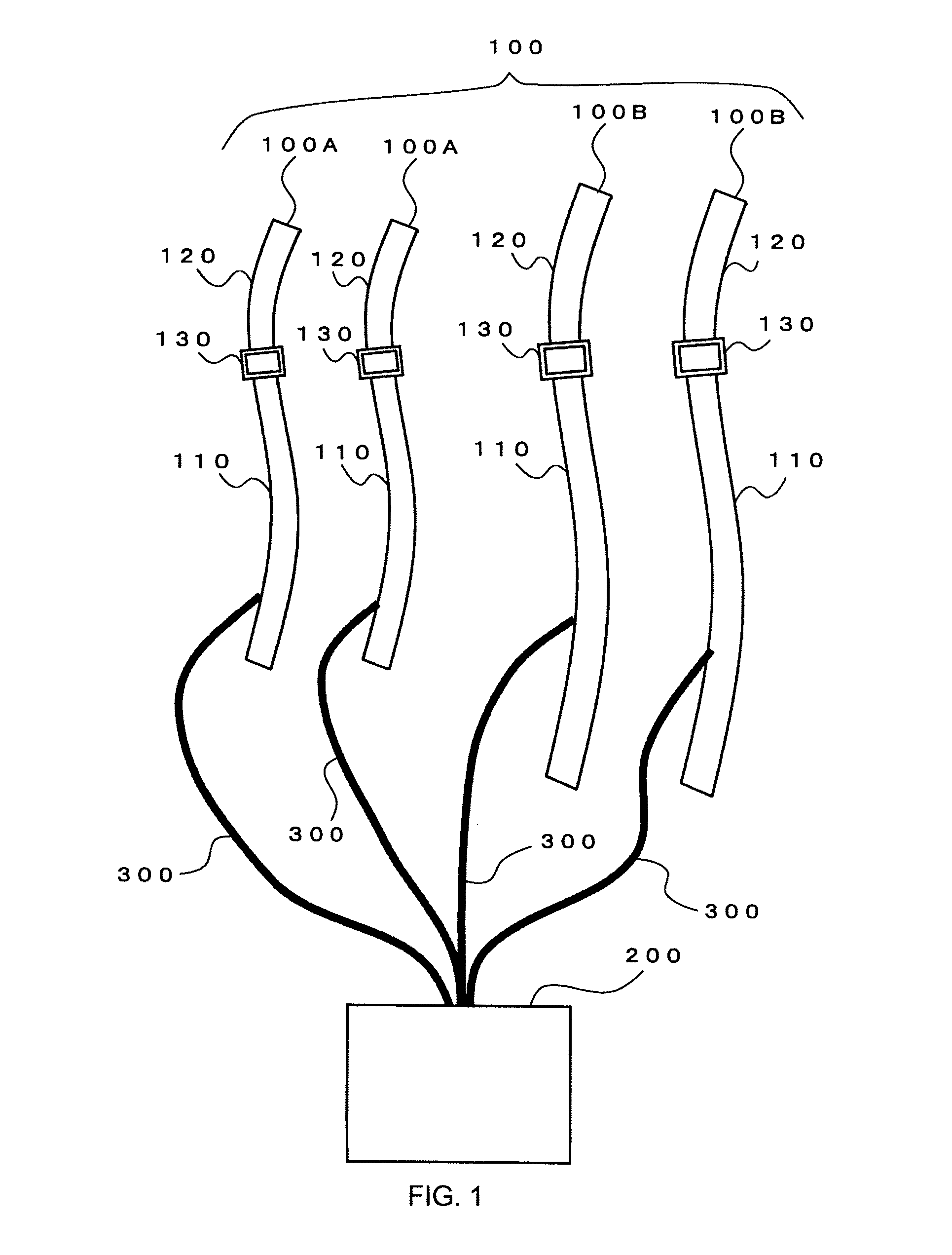
[0073]As shown in FIG. 1, the KAATSU muscle training apparatus according to this embodiment comprises a belt 100 and a main device 200. Each component of the belt 100 is designed so that it can be connected to the main device 200 through, for example, a connecting pipe 300 comprised of a rubber tube.

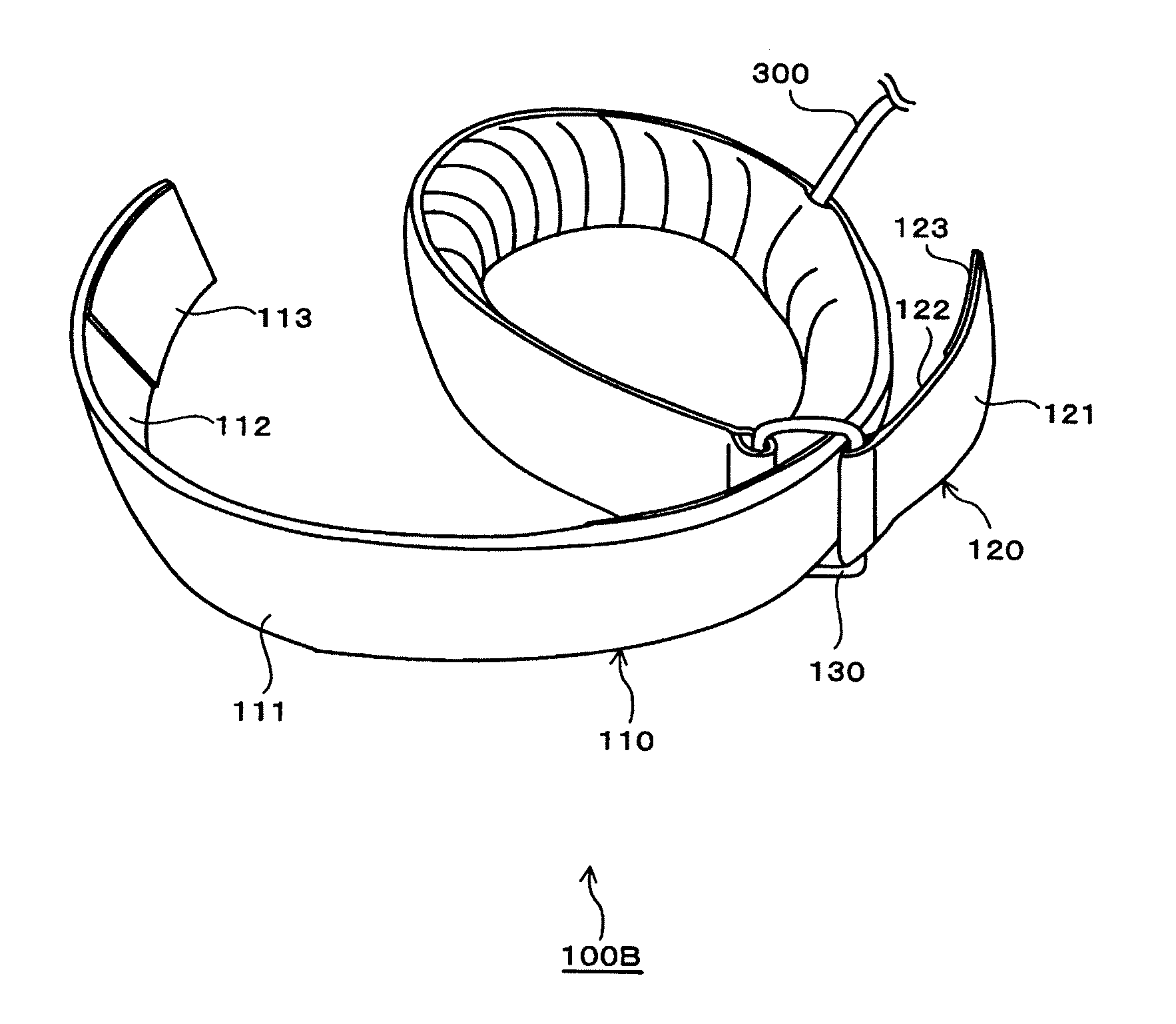
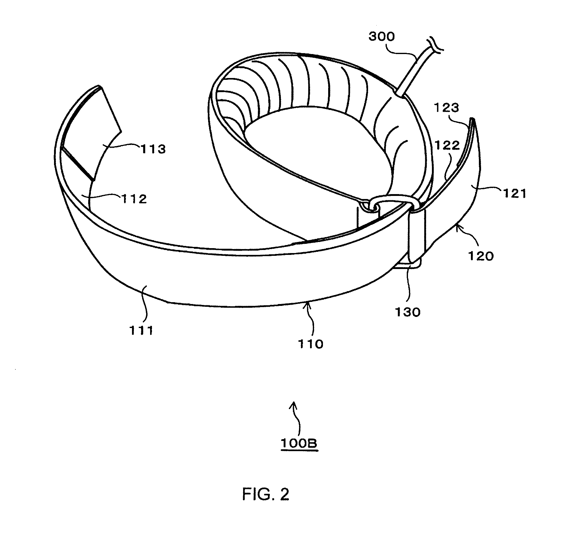
[0074]The belt 100 in this embodiment comprises a plurality of, more specifically, four components as shown in FIG. 1. The reason why there are four components of the belt 100 is to allow secure placement of the components of the belt 100 on the arms and legs, respectively, of a person (user) who uses the KAATSU muscle training method. The components of the belt 100 are tightened around a predetermined range (target compressed site) near the proximal portion of the arms and legs of the user.

[0075]Of the four components of the...

second embodiment

[0150]A belt 500 for the KAATSU muscle training in a second embodiment is shown in FIG. 10.

[0151]In short, the belt 500 in the second embodiment is equivalent to the belt 100 in the first embodiment except that there is no inflatable pneumatic bag 114. Accordingly, the belt 500 in the second embodiment is not intended to be combined with the main device 200.

[0152]The belt 500 in the second embodiment has no inflatable pneumatic bag, so that there is no air pressure of the inflatable pneumatic bag that can be used for changing the compression force to be applied to the target compressed site by the belt 500.

[0153]The belt 500 in the second embodiment is different from the belt 100 in the first embodiment only in the structure of the first band-shaped member 110, as shown in FIG. 10. The first band-shaped member 110 of the belt 500 has the thick fabric 111 and the thin fabric 112, as in the case of first band-shaped member 110 in the first embodiment, but they are joined to each other...


PUM


Abstract

To ensure easy and secure placement of a belt for KAATSU muscle training on a target compressed site near the proximal portion of a limb.A belt 100B has a longer first band-shaped member 110 and a shorter second band-shaped member 120 both of which have a band shape and are connected to a ring-shaped joint member 130 at their respective ends. In order to place the belt 100B on the target compressed site, the limb (right leg in this case) on which the belt 100B is expected to be placed is inserted into a loop of the first band-shaped member 110 formed by passing the end of the first band-shaped member 110 through an opening in the joint member 130, and the belt is moved up to the target compressed site. Then, the first band-shaped member 110 and the second band-shaped member 120 are pulled with both hands in the opposite directions. The belt 100B is placed on the target compressed site with the belt 100B being tensioned appropriately.

Description

TECHNICAL FIELD[0001]The present invention relates to a training apparatus for the muscle development. More particularly, the present invention relates to a KAATSU muscle training apparatus suitable for KAATSU muscle training that allows healthy people having no motor abnormalities as well as people having motor abnormalities to develop their muscles in an effective manner, and to a belt for such KAATSU muscle training.BACKGROUND OF THE INVENTION[0002]Dr. Yoshiaki Sato, the present inventor, has conducted researches and investigations for a long time in order to develop a muscle strength increasing method for easy, safe, and effective muscle development, and put together the accomplishments into a patent application having Japanese Patent Application No. 5-313949, which has been granted as Japanese Patent No. 2670421. In addition, the present inventor filed a U.S. patent application claiming priority of this application, which has been granted as U.S. Pat. No. 6,149,618.[0003]In add...

Claims


Application Information

Patent Timeline
IPC IPC(8): A63B21/008
CPCA61H9/0078A61H9/0092A61H11/00A61H2201/5038A61H2201/5071A61H2205/06A63B2220/56A63B21/0085A63B21/1434A63B21/1449A63B23/12A63B2213/006A61H2205/10A63B23/03508A63B23/0355A63B23/1209A63B69/0059A63B2208/053A63B2209/10A63B21/4011A63B21/4017A63B21/4025A63B2214/00
Inventor SATO, YOSHIAKI
Owner KAATSU JAPAN
Learn More