Catheter

a catheter and catheter technology, applied in the field of catheters, can solve the problems of limited curvature angle, complicated catheter structure, limited size of the area that can be navigated, etc., and achieve the effects of simple and fast setup, easy navigation, and minimal risk of injury

Inactive Publication Date: 2011-06-07
SIEMENS HEALTHCARE GMBH
View PDF96 Cites 25 Cited by
  • Summary
  • Abstract
  • Description
  • Claims
  • Application Information

AI Technical Summary

Benefits of technology

[0007]Using the flexural element usefully provided on the catheter tip side, a curvature of the catheter can be achieved in a simple manner when required. Said curvature allows the catheter to adapt to the subsequent course of the blood vessel and to be threaded in a simple manner into a branch of a blood vessel, for example. For this purpose, the flexural element, which is flexible in a non-pressurized state, has simply to be filled with the filling medium in order to build up the pressure. As a result of the increasing pressure the flexural element increasingly stiffens and assumes a predetermined curved shape. According to the filling level, any intermediate shape ranging from completely flexible to completely stiff can be set, there being various degrees of rigidity. Depending on the embodiment of the flexural element, any desired angles of curvature can therefore be set in the stiffened state.
[0008]It is useful if a plurality of individually controllable flexural elements are provided so that, according to the position of the catheter and the required curvature, a required flexural element can be activated and the catheter or, as the case may be, the catheter tip, which in this catheter is sufficiently flexible and so designed to avoid a risk of injury when the catheter is advanced, can flex in the right direction.
[0009]In this case the flexural elements can be arranged in such a way that the predetermined directions of deformation are aligned to different directions. The multiple flexural elements thus all curve in a different direction, with the result that a high degree of flexibility is achieved with respect to the catheter tip deformation. According to a first invention alternative the flexural elements can be arranged sequentially essentially in the center of the catheter relative to the longitudinal axis of the catheter. In other words the flexural elements, which are dimensioned to be relatively short in this case, are arranged one after the other in series. Furthermore it is also possible that at least some of the flexural elements are disposed in a distributed arrangement about the longitudinal axis of the catheter. In this case, therefore, the flexural elements are staggered radially outward; they are disposed in a distributed arrangement around the internal catheter cavity in which, for example, signal lines or similar are run. In this way a fully variable tip deformation can be set in particular for different preferred directions of flexure.
[0011]A flexural element itself is usefully made from a non-elastic material. In order to achieve the defined shape in the filled state, the walls thereof are non-symmetrical in design, that is to say the lengths of the side walls are different, with the result that a curved shape is produced in the filled state. Usefully, polyurethane or polytetrafluoroethylene is utilized for this purpose, in other words materials that are non-elastic, thereby avoiding any stretching of the material that would result in an approximation to a spherical shape.
[0013]Since, as described above, the simple means of navigation is based on the situation-dependent activation of the flexural element or elements, a development of the inventive idea for simple and fast setup of the catheter, in other words when it is needed and is to be used, provides that it has a central connection device for a feed device for the filling medium, at which connection device the or all lines for the filling medium leading to the flexural element or elements converge. Thus, a defined connection point for all fluid or gas feed lines is provided, usefully in the form of a simple plug-in connection to which a corresponding counterpart can be connected as part of a feed device.
[0014]All in all, the catheter according to the invention allows easy navigation without a large outlay in terms of external equipment. All that is required is a feed device which simultaneously handles control functions in order to activate the flexural elements. In particular with a distribution of a plurality of flexural elements over a specific length of the catheter, control of the catheter curvature is also advantageously possible not only at the end of the catheter, but quasi segmentally or approximately randomly at different points of the catheter. It is also conceivable to be able to vary the flexibility or stiffness of the catheter over the entire length along which the flexural elements are distributed, or only over a part thereof. For it is of course possible to put a plurality of flexural elements, of a segment for example, under pressure simultaneously so that their forces cancel one another out and the catheter does not deform but stiffens in sections. It is therefore possible to stiffen the catheter over the entire length along which the flexural elements are distributed, or only over a section thereof. In this way it is possible to minimize the risk of injury, where this is necessary because of the anatomical conditions, as well as to optimize the controllability and “pushability”, where this is possible from the point of view of risk of injury. The controllable curvature at any point of the catheter over the range of the flexural elements also results in the curvatures along the vascular structures exerting no deformation force from the catheter on the vascular walls, since of course there is also the possibility of producing corresponding vascular curvatures on the catheter side, even if the catheter tip has already long since passed this section. The shape of the catheter thus adapts itself as far as possible to the actual shape of the blood vessel, and the vascular walls are not too greatly irritated and deformed via the catheter. This reduces the risk of injury during interventions.

Problems solved by technology

The disadvantage thereof is firstly the complexity of the catheter and secondly the limited angle of curvature that can be set.
However, the above method requires a substantial outlay in terms of technology, equipment and cost, and furthermore the size of the area that can be navigated is limited due to the dimensions of the magnetic field.

Method used


Image

  • Catheter
  • Catheter
  • Catheter

Examples


Embodiment Construction

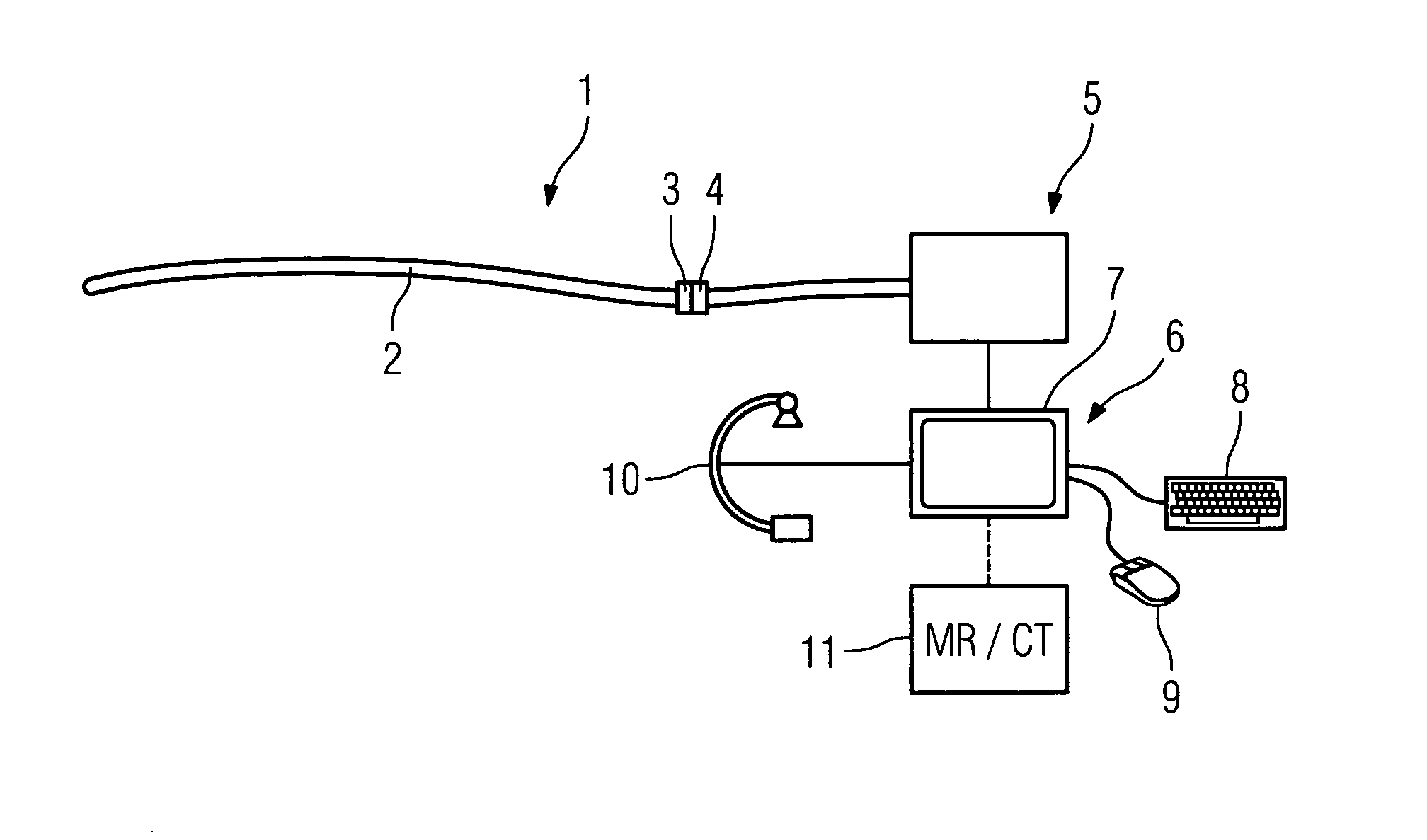
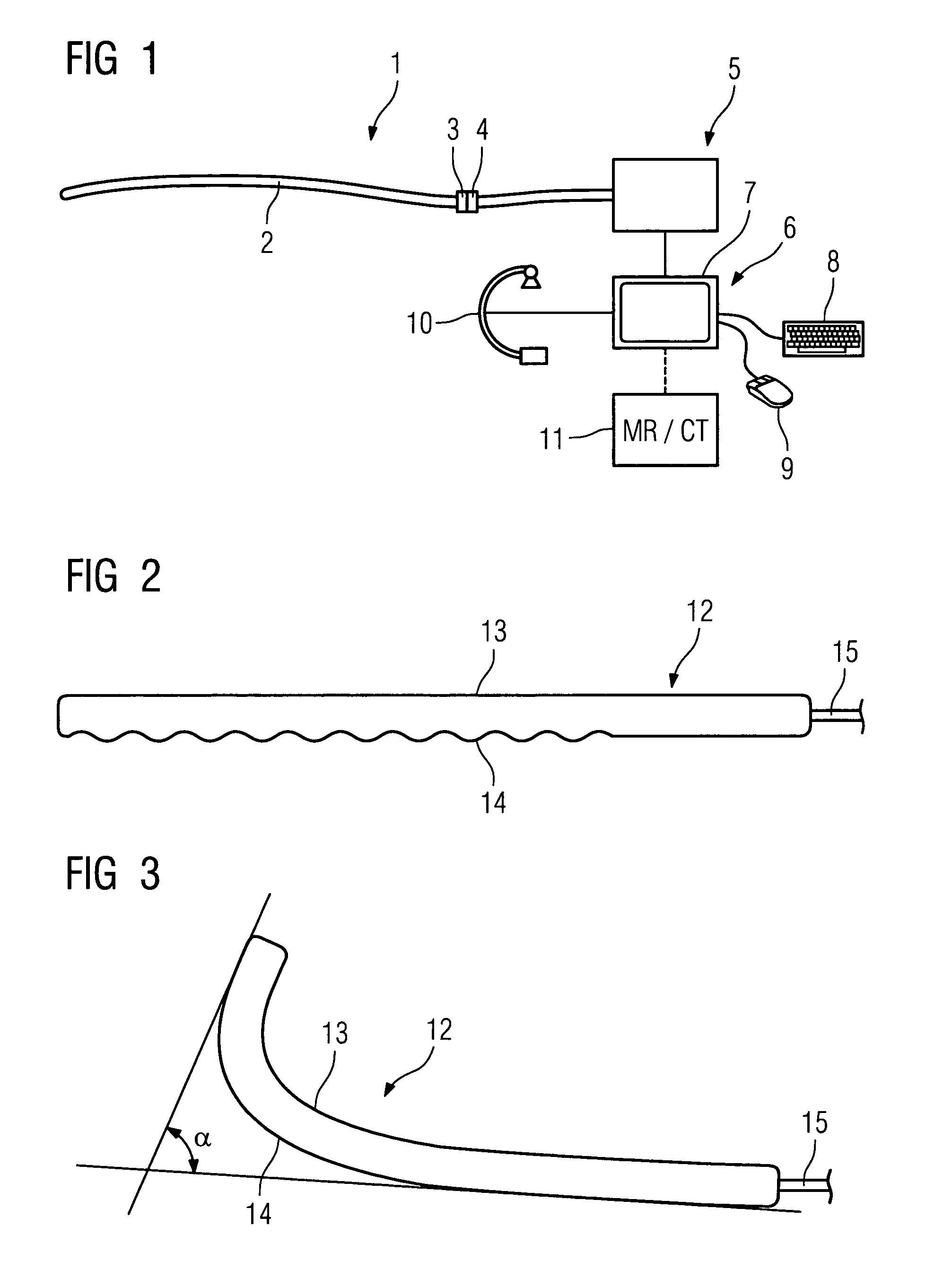
[0028]FIG. 1 shows a catheter device 1 according to the invention comprising a catheter 2, at the free end of which (i.e. the end that is not to be inserted into the patient) there is provided a connection device 3 which is coupled to a connection device 4 that forms part of a feed device 5 for a liquid or gaseous filling medium. By means of said feed device 5, a liquid or gaseous filling medium can be supplied to the individual flexural elements which are integrated into the catheter and which are hereinafter described in further detail. The feed device 5 is coupled to an input device 6 comprising a monitor 7, a keyboard 8 and a mouse 9. By means of said device, the operator, referring to an image displayed on the monitor 7, said image being supplied for example by an X-ray image taken in parallel by an X-ray device 10 during the invasive procedure, or where appropriate using an image data set 11, obtained for example by magnetic resonance tomography or computer tomography, can spe...


PUM


Abstract

Catheter for inserting into a hollow organ, in particular a blood vessel, wherein at least one tube- or balloon-like flexural element (12, 12a, . . . , 12l) which can be filled with a filling medium is provided inside the catheter, which flexural element is flexible in the non-pressurized state and stiffens as a result of pressure buildup internally and assumes a predetermined curved shape.

Description

CROSS REFERENCE TO RELATED APPLICATIONS[0001]This application claims priority to the German application No. 10 2004 003 166.5, filed Jan. 21, 2004 which is incorporated by reference herein in its entirety.FIELD OF INVENTION[0002]The invention relates to a catheter for inserting into a hollow organ, in particular a blood vessel.BACKGROUND OF INVENTION[0003]Flexible catheters which are advanced through arteries or veins are used for intravascular or intracardial treatment. At the tip or side of said catheters functional mechanisms are provided, for example to stimulate or cauterize tissue or to conduct electrical signals. In order to be able to deliver the catheter to the correct positions in the cardiac or vascular system, the catheters have to be moved and guided by the physician. Such guidance has to be precise, fast and highly flexible, in particular because the vascular system is a convoluted system that contains a number of bends. Most of the time during treatment is taken up by...

Claims


Application Information

Patent Timeline
Patent Type & Authority Patents(United States)
IPC IPC(8): A61B6/00A61F2/958A61M25/00A61M25/01A61M25/092
CPCA61M25/0041A61M25/0155A61M25/0105
Inventor KLEEN, MARTIN
Owner SIEMENS HEALTHCARE GMBH
Why Eureka
Try Eureka