Diaphragm pump, and exhaust-gas aftertreatment system having a diaphragm pump

a diaphragm pump and exhaust gas aftertreatment technology, which is applied in the direction of flexible member pumps, machines/engines, positive displacement liquid engines, etc., can solve the problems of increased wear, undesirable noise generation, frictional forces, etc., and achieve the highest possible number of windings, low noise, and easy and cost-effective manufacturing

Inactive Publication Date: 2013-11-21
ROBERT BOSCH GMBH
View PDF7 Cites 6 Cited by
  • Summary
  • Abstract
  • Description
  • Claims
  • Application Information

AI Technical Summary

Benefits of technology

[0006]Based on the prior art specified above, the aim of the invention is to provide a compact diaphragm pump which operates with low noise and low friction, can be actuated via an electromagnet and furthermore has a high degree of efficiency.
[0010]According to one modification, the valve plate and / or the working diaphragm comprise damping grooves which are preferably disposed along the circumference. In the case of a circular layout of the working chamber, the damping grooves are preferably arranged in circles that are concentric to one another. The damping grooves dampen the movement of the armature because in order to build up pressure in the working chamber, the medium has to be displaced from the damping grooves.
[0014]The cup-shaped receiving spaces can be worked into a flat armature plate by means of a shaping process. The armature is preferably a stamped / bent part which can be easily and cost effectively manufactured.
[0015]It is furthermore proposed that the electromagnet is a DC solenoid. Provision can alternatively or additionally be made for the electromagnet to comprise a coil having two inside diameters. In so doing, the highest possible number of windings can be achieved.
[0016]On the basis of the advantages of an inventive diaphragm pump specified above, such a pump is particularly suited for use in an exhaust-gas aftertreatment system for delivering an exhaust gas aftertreatment medium, in particular an aqueous urea solution. The diaphragm pump thus prevents the electromagnet from coming in contact with the medium to be delivered; thus enabling said electromagnet to be protected from corrosion. In addition, an exhaust-gas aftertreatment system comprising an inventive diaphragm pump for delivering an exhaust-gas aftertreatment medium, in particular an aqueous urea solution, is therefore proposed. Besides the previously specified advantage, the operation of the pump with low noise and low friction and the compact construction advantageously affect the exhaust-gas aftertreatment system.

Problems solved by technology

In addition, the guide area of the piston and / or the armature is subjected to an increased amount of wear due to friction.
On account of the length of the piston, said piston can furthermore tilt, whereby the frictional forces and consequently the wear increase.
The lifting motion of the armature is delimited by the housing of the electromagnet, which can lead to an undesirable noise generation when the armature strikes the housing.

Method used


Image

  • Diaphragm pump, and exhaust-gas aftertreatment system having a diaphragm pump
  • Diaphragm pump, and exhaust-gas aftertreatment system having a diaphragm pump
  • Diaphragm pump, and exhaust-gas aftertreatment system having a diaphragm pump

Examples


Embodiment Construction

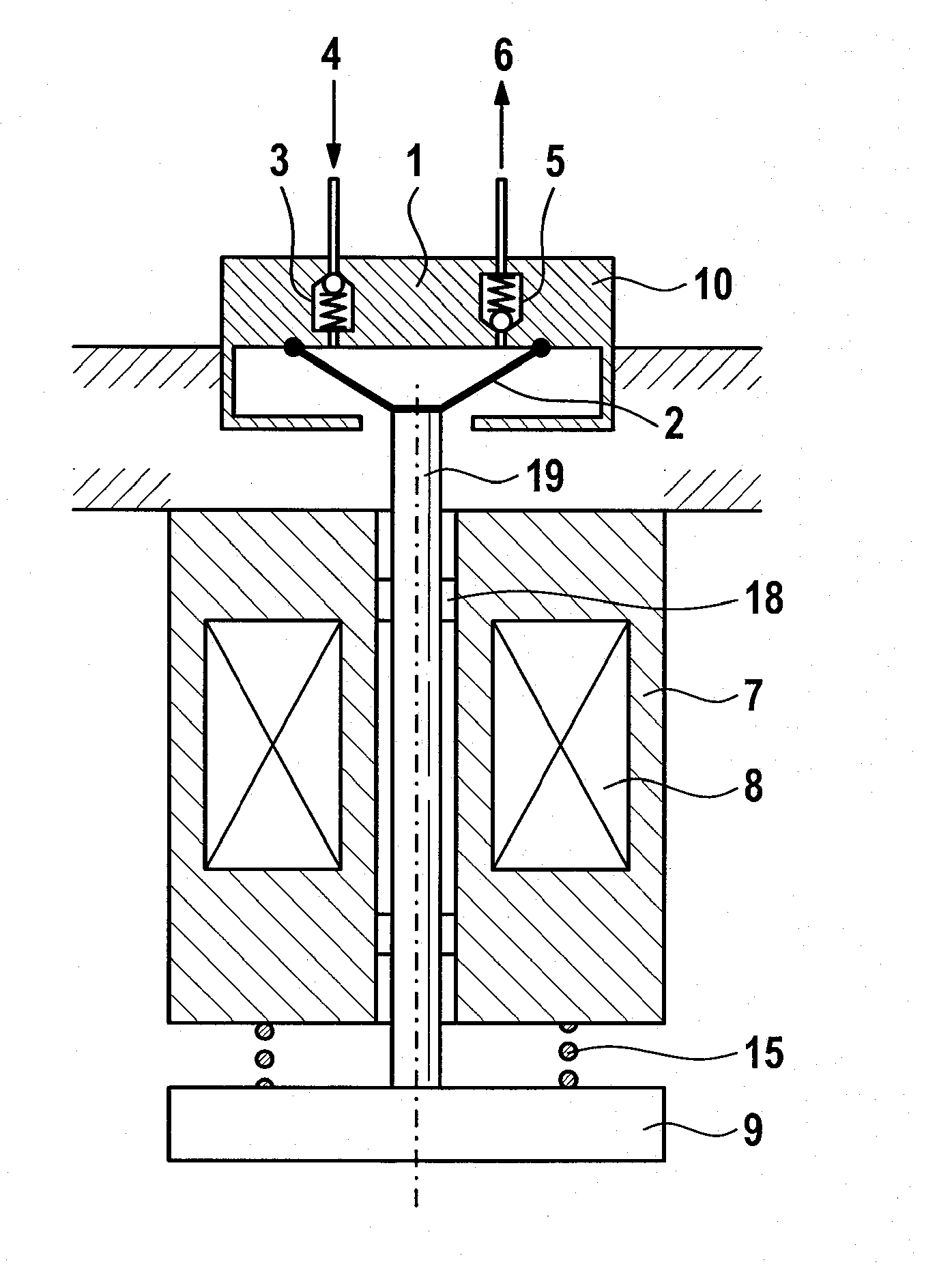
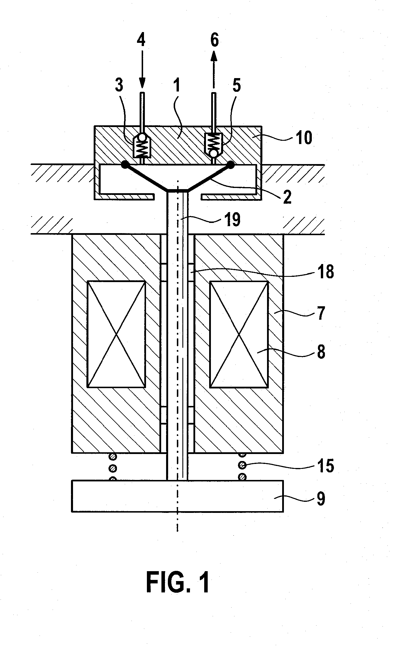
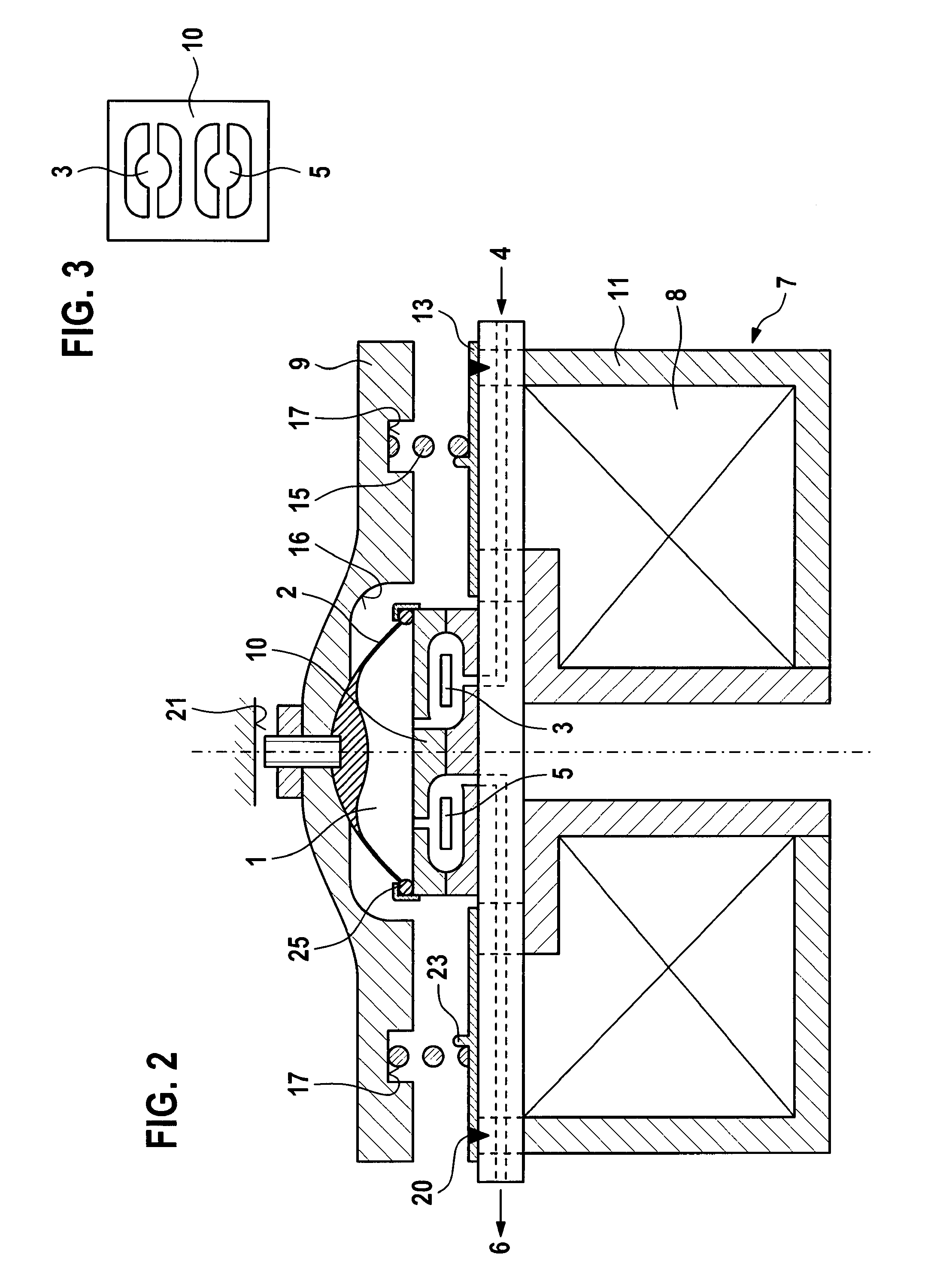
[0028]The disadvantages of a known diaphragm pump from the prior art will now once again be made clear with the aid of the schematic cross-section through such a pump. The pump depicted has a working chamber 1 which is delimited from a working diaphragm 2 as well as from a valve plate 10. The valve plate 10 accommodates a first valve for connecting the working chamber 1 to an inlet 4 as well as a second valve 5 for connecting the working chamber 1 to an outlet 6. The valve plate 10 is mounted on a plate-shaped supporting element which supports an electromagnet 7 as the drive of the pump on the side facing away from the valve plate 10. The electromagnet comprises a coil assembly 8 as well as an armature 9 which interacts with the coil assembly 8 and is disposed on the side of the electromagnet 7 facing away from the valve plate 10. The armature 9 comprises an armature pin 19 which is passed through the coil assembly 8 and mounted in an axially displaceable manner via guides 18. When ...


PUM


Abstract

Diaphragm pump for delivering a fluid, in particular an exhaust-gas aftertreatment medium, such as an aqueous urea solution for example, comprising a working chamber (1) which is delimited by a working diaphragm (2) and which can be connected via a first valve (3) to an inlet (4) and via a second valve (5) to an outlet (6), and an electromagnet (7) which comprises a coil assembly (8) and an armature (9) which interacts with the coil assembly (8) and is operatively connected to the working diaphragm (2). According to the invention, the valves (3, 5) are configured in a valve plate (10) which is arranged between the coil assembly (8) and the armature (9). Exhaust-gas aftertreatment system having a diaphragm pump of this type.

Description

BACKGROUND OF THE INVENTION[0001]The invention relates to a diaphragm pump for delivering a fluid, in particular an exhaust-gas aftertreatment medium, such as, for example, an aqueous urea solution. In addition, the invention relates to an exhaust-gas aftertreatment system comprising such a diaphragm pump.[0002]Diaphragm pumps, in particular diaphragm pumps that can be used in exhaust-gas aftertreatment systems, have already been disclosed by the prior art. The German patent application DE 10 2008 043 309 A1 discloses a diaphragm pump having a multi-parted pump housing, the working membrane of which is clamped between two housing parts and can be axially actuated by an electric motor via an eccentric and connecting rod. In order to fix the working diaphragm, the housing parts are axially clamped to one another.[0003]A further diaphragm pump is disclosed by the published German patent application DE 10 2005 003 583 A1. In this case, the working diaphragm is not actuated via an eccent...

Claims


Application Information

Patent Timeline
Patent Type & Authority Applications(United States)
IPC IPC(8): F04B43/04
CPCF04B43/04F04B17/04
Inventor HAEBERER, RAINER
Owner ROBERT BOSCH GMBH
Why Eureka
Try Eureka