Filler plug for hydraulic device

a technology for hydraulic devices and fillers, which is applied in the direction of threaded fasteners, screws, bolts, etc., can solve the problems of b>4/b> collapse, and achieve the effects of high pressure, high tightening torque, and high sealing performan

Active Publication Date: 2013-03-14
KAWASAKI HEAVY IND LTD
View PDF13 Cites 6 Cited by
  • Summary
  • Abstract
  • Description
  • Claims
  • Application Information

AI Technical Summary

Benefits of technology

[0032]According to the filler plug for the hydraulic device according to the present invention, by setting the dimensionless value of head portion height to 0.4 to 0.7, the filler plug can be tightened with respect to the internal thread portion formed in the through hole at a high tightening torque and can realize high-performance sealing of the through hole in which the pressure is high. In addition, the height of the head portion can be made small, and the depth of the funnel-shaped inclined inner peripheral surface formed in the through hole of the hydraulic device can be made small. With this, the thickness of the hydraulic device can be made small, so that the reductions in the size and cost of the hydraulic device can be realized.

Problems solved by technology

However, if the tightening torque is high, the engaging recess 4 collapses.

Method used


Image

  • Filler plug for hydraulic device
  • Filler plug for hydraulic device
  • Filler plug for hydraulic device

Examples


Embodiment Construction

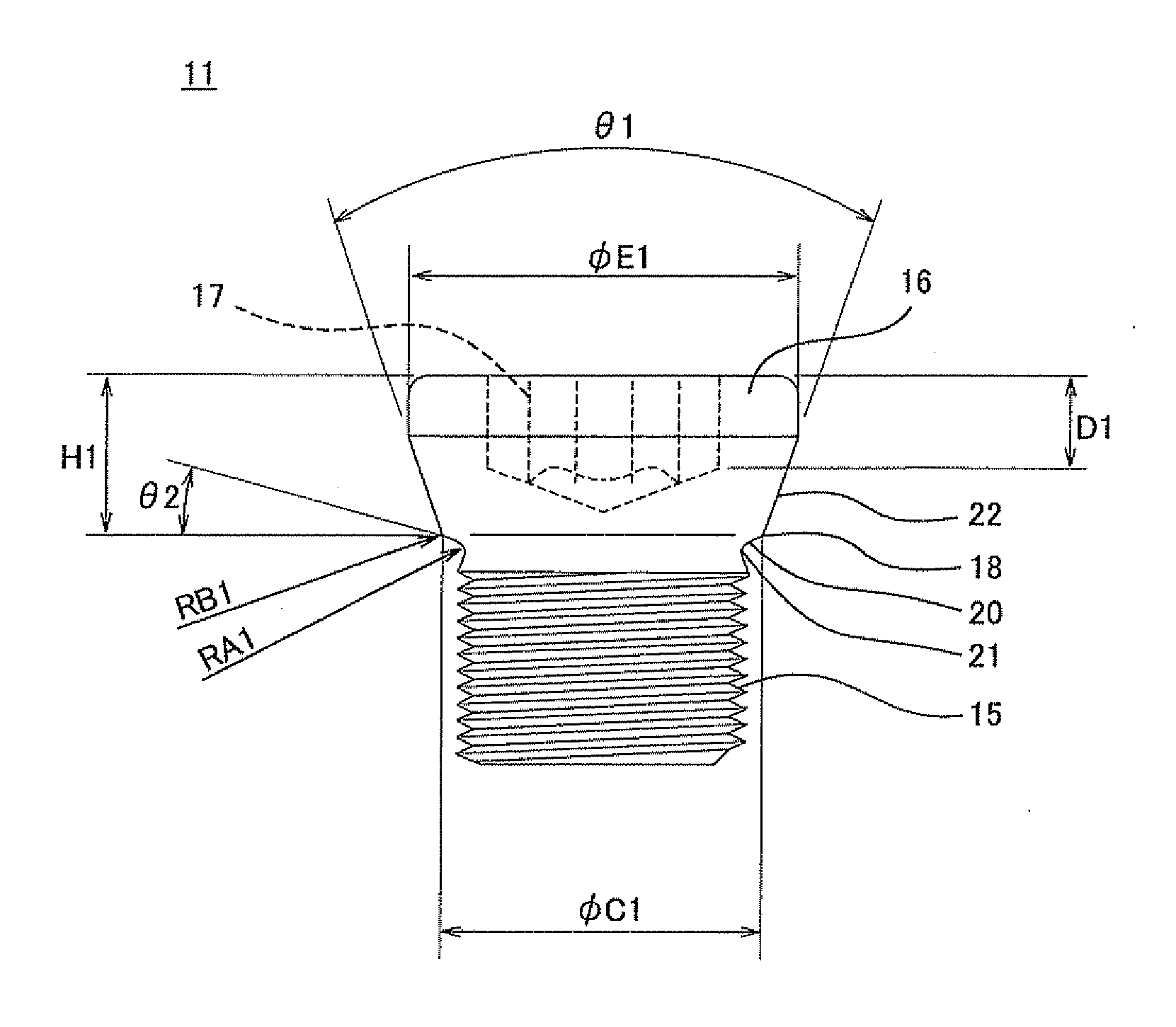
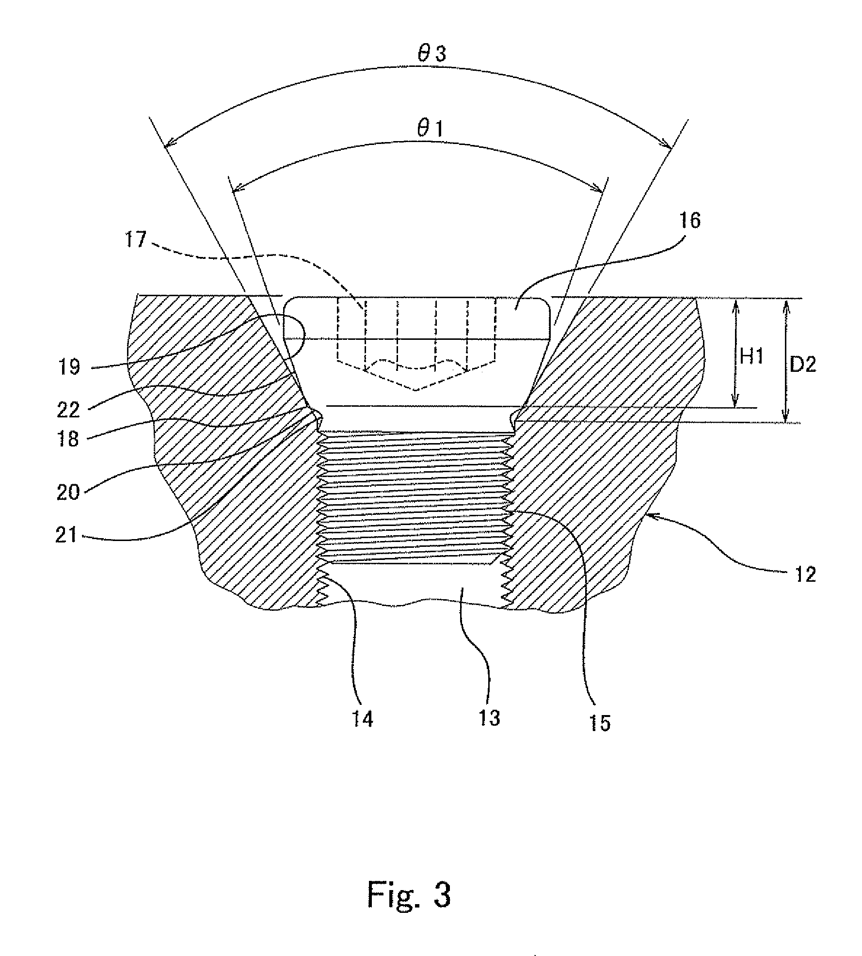
[0038]Hereinafter, one embodiment of a filler plug for a hydraulic device according to the present invention will be explained in reference to FIGS. 1 to 4. As shown in FIG. 3, a filler plug 11 for a hydraulic device can realize high-performance sealing of an opening end portion of, for example, an oil passage 13 (through hole) formed in a hydraulic device 12, such as a hydraulic valve or a hydraulic pump, by tightening an external thread portion 15 of the filler plug 11 with respect to an internal thread portion 14 of the oil passage 13 at a high tightening torque. A material of the filler plug 11 is steel, such as SCM435 that is thermal refined steel, but the other metal may be used.

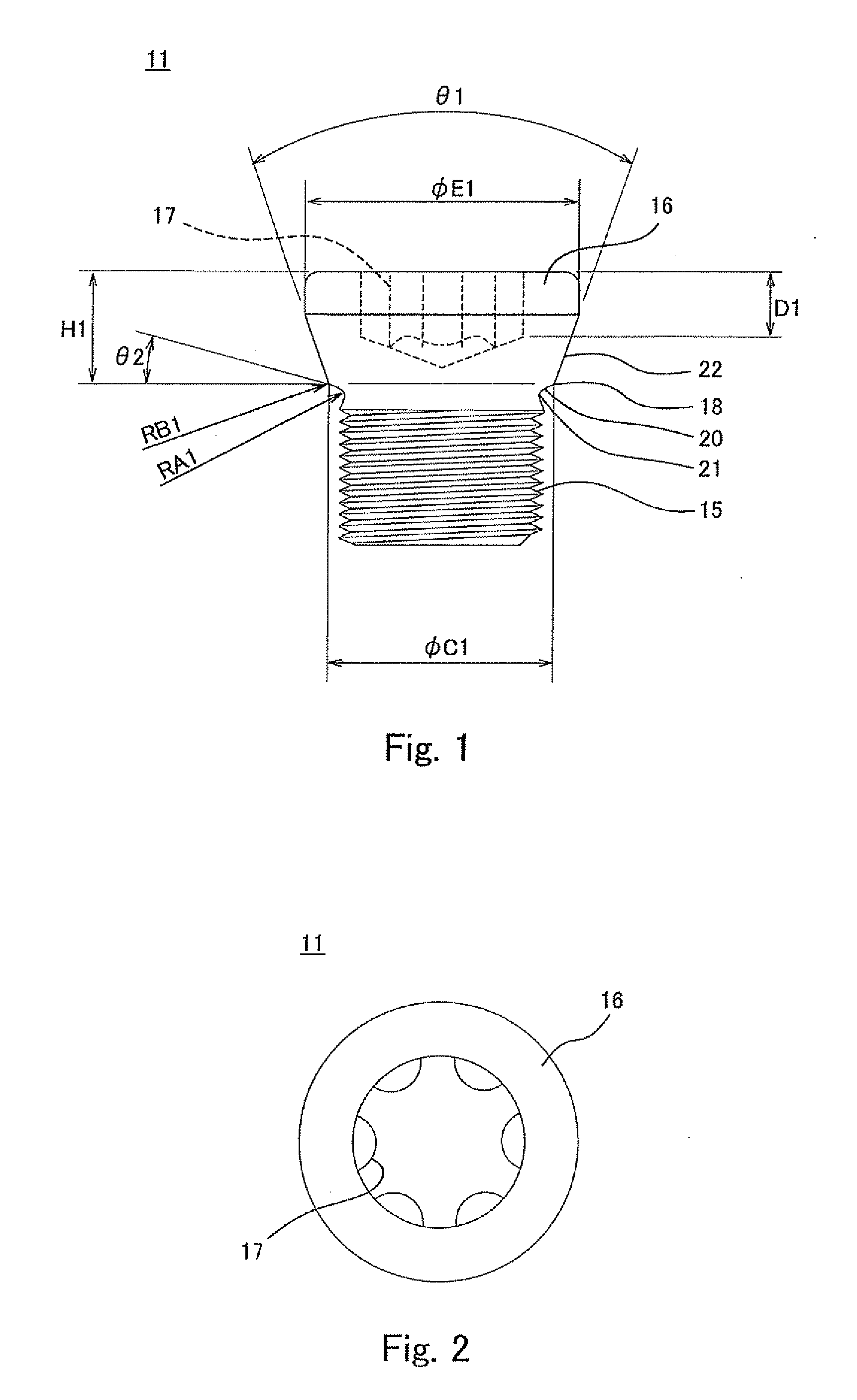
[0039]As shown in FIGS. 1 and 2, the filler plug 11 for the hydraulic device includes the external thread portion 15. A head portion 16 having a larger diameter than the external thread portion 15 is formed on an upper end portion of the external thread portion 15. An engaging recess 17 is formed on an...


PUM


Abstract

A filler plug is configured such that: a head portion is formed on an upper end of an external thread; a sealing portion formed at the head portion strongly contacts a funnel-shaped inclined inner peripheral surface formed at one end of an internal thread of a hydraulic device oil passage by tightening the external thread with respect to the internal thread; an upper peripheral surface of the sealing portion is tapered; a circular constricted portion is formed between the sealing portion and the upper end of the external thread; and a dimensionless value of a head portion height H1 from an upper surface of the head portion to the sealing portion, that is, a dimensionless value obtained by dividing the head portion height H1 by a nominal designation value of the external thread portion, ranges from 0.4 to 0.7.

Description

TECHNICAL FIELD[0001]The present invention relates to a filler plug for a hydraulic device, the filler plug being capable of sealing a through hole, such as a process hole (waste hole), created to form, for example, an oil passage in a hydraulic device.BACKGROUND ART[0002]One conventional example of the above-described filler plug for the hydraulic device is shown in FIG. 5 (see PTL 1, for example). As shown in FIG. 5, a filler plug 1 for a hydraulic device includes an external thread portion 2. A head portion 3 having a larger diameter than the external thread portion 2 is formed on an upper end portion of the external thread portion 2. An engaging recess 4 is formed on an upper end surface of the head portion 3. The engaging recess 4 is, for example, a hexagon socket.[0003]As shown in FIG. 5, when sealing an opening end portion of an oil passage 5 (through hole) formed in the hydraulic device by using the filler plug 1, a hexagonal wrench (tool) is caused to engage with the engagi...

Claims


Application Information

Patent Timeline
Patent Type & Authority Applications(United States)
IPC IPC(8): F16J13/12F16B35/00
CPCF16B33/004F16L55/1108F16J15/04F16J13/12F16B35/00
Inventor SAKAI, RYUJIWADA, HISAOIMAI, TATSUYA
Owner KAWASAKI HEAVY IND LTD
Why Eureka
Try Eureka