Stent and Method and Device for Fabricating the Stent

a technology of stent and stent body, which is applied in the field of stent, can solve the problems of symmetrical curvature, inability to selectively treat the proximal end of the stent, and adverse effects of fluid flow, so as to reduce the risk of unwanted neointimal hyperlasia and arteriosclerosis, prevent injury, and minimize the pressure on the vascular wall

Active Publication Date: 2012-08-23
BIOTRONIK AG
View PDF7 Cites 5 Cited by
  • Summary
  • Abstract
  • Description
  • Claims
  • Application Information

AI Technical Summary

Benefits of technology

[0012]According to the invention, a stent is provided that has a tubular, individual-struts-comprising lattice structure, wherein the stent has at least one strut, of which at least one longitudinal section runs with at least one directional component in the radial circumferential direction of the stent, and wherein the radially outward-facing (mural) surface of the longitudinal section of the strut is curved only around one longitudinal axis of the stent. According to the invention, the surface of the strut's longitudinal section (luminal) facing towards the inside of the stent has a curvature such that the cross section of the strut is fluidically optimized. The invention thus relates to the design of a strut, or also only of a longitudinal section of a strut, that runs with at least one directional component in a radial circumferential direction of the stent. This means that the strut, or its longitudinal section, runs parallel to a tangent applied to the circumference of the stent, or has one component that is oriented in this direction. What is excluded according to the invention, however, are the longitudinal strut sections that run only parallel to the longitudinal axis of the stent. This fundamentally distinguishes the stent according to the invention from the embodiments shown in EP 0 824 903 A1. These types of struts according to the invention can be easily cut from a tube by laser. What is understood by the strut cross section is that cross section which is produced by a section in the longitudinal axis of the stent through the longitudinal section of the strut with one directional component in the radial circumferential direction, in other words, performed in the direction of the longitudinal axis of the stent. According to the invention, the strut in cross section has only on the luminal surface in its longitudinal direction a curvature which is designed to prevent turbulences of the blood flow passing through the stent, and thus prevent deposits. On the mural side, the strut has no curvature in the cross section running in the longitudinal direction of the stent. This design is particularly advantageous since the mural contact surface of the strut on the vascular wall is not thereby reduced, and thus the pressure of the strut on the vascular wall is limited, thereby reducing the risk of damage to the vessel.

Problems solved by technology

In addition, electropolishing is used to treat the entire support structure, with the result that it is not possible to perform a selective treatment of the proximal end of the stent.
It is the curvature of the mural surface in particular that is disadvantageous in that a strut curved in this way penetrates more deeply into the vascular wall during dilatation, thereby damaging this wall to a greater extent.
It is well known that symmetrical curvatures have an adverse effect on fluid flows in so far as they are unable to produce a laminar flow.
Another disadvantage of the strut cross sections referenced in this document is the reduction in its axial section modulus which in particular has a disadvantageous effect on the strength of the stent in response to increased bending stress.
Particularly in the case of novel stents composed of magnesium alloys, relatively large wall thicknesses are required for reasons of strength, with the result that the cross-sectional shapes of the struts disclosed in EP 0 824 903 A1 are not usable for such stents without unduly reducing the radial strength of the stent.
This is disadvantageous, however, because the sectional area of flow of the blood vessel is reduced thereby, which effect results in turbulences and increased formation of deposits.

Method used


Image

  • Stent and Method and Device for Fabricating the Stent
  • Stent and Method and Device for Fabricating the Stent
  • Stent and Method and Device for Fabricating the Stent

Examples


Embodiment Construction

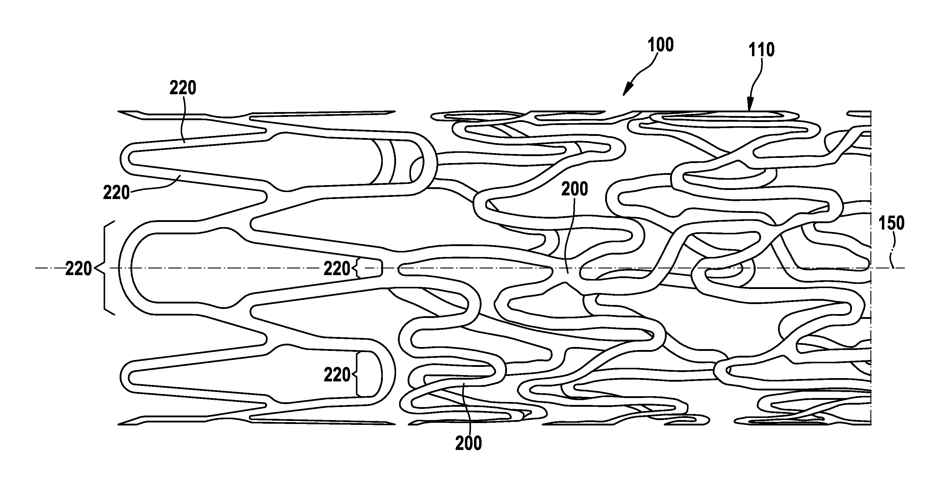
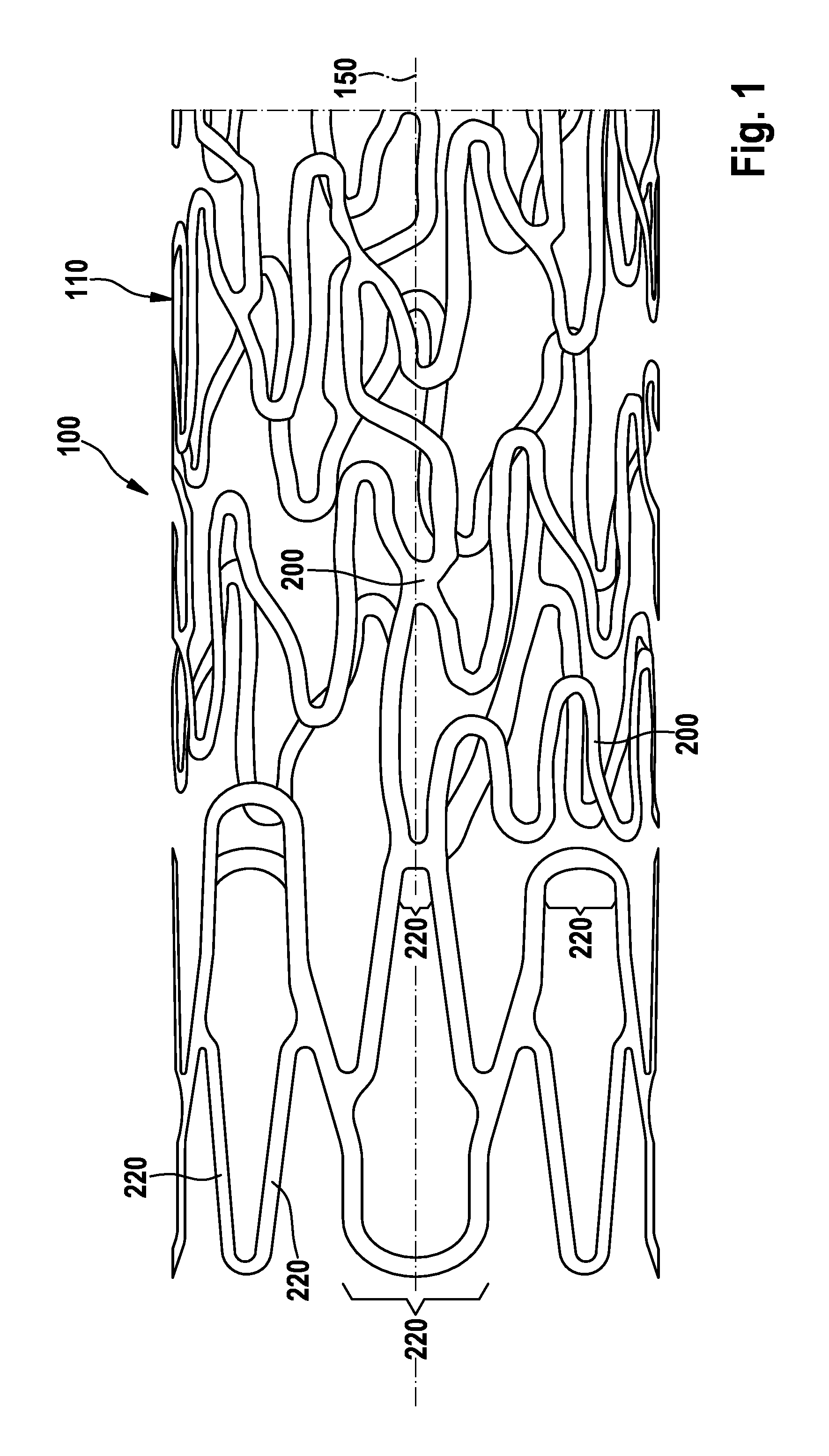
[0044]FIGS. 1 and 2 illustrate struts 200 such as those conventionally used in the support structure or lattice structure 110 of a stent 100. The invention here is not restricted to the design of the lattice structure 110 illustrated in FIG. 1; instead, the invention can comprise all stent structures that have struts and in which the longitudinal sections have at least one directional component that runs in the radial circumferential direction of the stent. This refers to those longitudinal sections 220 that, as shown in FIG. 1, do not run parallel to the longitudinal axis 150 of stent 100. This thus refers to longitudinal sections 220 that obviously run in a radial circumferential direction but also to the longitudinal sections that run obliquely relative to the longitudinal axis since these longitudinal sections have also a directional component that runs perpendicular to the longitudinal axis.

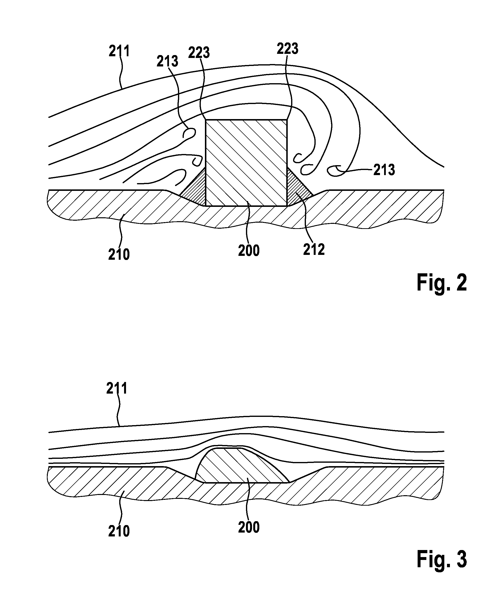
[0045]It is thus evident in FIG. 2 that the surfaces of the strut facing the outside of ...


PUM

PropertyMeasurementUnit
thicknessaaaaaaaaaa
thicknessaaaaaaaaaa
thicknessaaaaaaaaaa

Abstract

Stent, as well as a method and device for fabricating the stent, wherein the stent has a tubular lattice structure comprising individual struts and at least one strut of which at least one longitudinal section runs with at least one directional component in the radial circumferential direction of the stent, wherein the surface of the longitudinal section facing the outside of the stent is curved only about the longitudinal axis of the stent. According to the invention, the surface of longitudinal section of the strut, which surface faces the inside of the stent, has such a curvature that the strut cross section is fluidically optimized.

Description

CROSS-REFERENCE TO RELATED APPLICATIONS[0001]This application claims benefit of priority to German patent application number DE 10 2008 038 367.8, filed on Aug. 19, 2008; the contents of which are herein incorporated by reference in their entirety.FIELD OF THE INVENTION[0002]This invention relates to a stent that comprises struts, a method of fabricating the stent, as well as a device for implementing the method.BACKGROUND OF THE INVENTION[0003]Stents are typically endovascular prostheses that are used for the therapy applied to stenoses. They essentially comprise a support structure by which the wall of a vessel, such as, for example, an artery, is braced so as to ensure sufficient flow through the vessel. In addition, an aneurysm can be bridged by the stent. During implantation, the stent is inserted in a cornpressed state into the vessel and then expanded at the site to be treated. Expansion of the stent is typically effected by means of a balloon catheter that has been previousl...

Claims


Application Information

Patent Timeline
Patent Type & Authority Applications(United States)
IPC IPC(8): B24B1/00A61F2/06A61F2/91A61F2/915
CPCA61F2/91A61F2002/9155A61F2002/068A61F2/915A61F2/82B24C3/32B24C3/325B24C5/04
Inventor HARDER, CLAUS
Owner BIOTRONIK AG
Why Eureka
Try Eureka