Thin-film magnetic head with through holes reaching medium-opposed surface

a thin film, magnetic head technology, applied in the direction of maintaining the head carrier alignment, manufacturing the head surface, instruments, etc., can solve the problems of head performance degrading, affecting the performance of the head, and the magnetic spacing is likely to vary, so as to achieve stably controlled magnetic spacing, stably performed, and controlled pressure between the head and the medium

Inactive Publication Date: 2011-12-27
TDK CORPARATION
View PDF18 Cites 4 Cited by
  • Summary
  • Abstract
  • Description
  • Claims
  • Application Information

AI Technical Summary

Benefits of technology

[0011]Therefore, an object of the present invention is to provide a thin-film magnetic head in which the magnetic spacing can be controlled appropriately by stably adjusting the pressure working between the thin-film magnetic head and the magnetic recording medium according to the change of conditions such as the change over time, and a magnetic tape apparatus provided with the just-described thin-film magnetic head.
[0015]In this thin film magnetic head with the through hole, gas (air) in the through hole is dragged out into between the head and the magnetic recording medium based on Venturi effect when the medium moves. As a result, the laminar air flow generated between the head and the moving medium can be adjusted; and thus, the pressure between the head and the medium can be stably controlled. Here, the degree of the pressure can be determined by appropriately setting the number of the through holes and the shape and cross-sectional area of each of through holes.
[0016]The thin-film magnetic head according to the present invention preferably further comprises at least one flow-amount control means for controlling the flow amount of gas that flows via the at least one through hole. The flow-amount control means acts as a valve by which varied is the cross-sectional area of at least a portion of the through hole, or a valve that opens and closes the opening or the coupling end of the through hole. As a result, the laminar air flow generated between the thin-film magnetic head and the magnetic recording medium can be controlled; and thus, the pressure working between the head and the medium can be dynamically adjusted according to the change of conditions such as the change over time. Consequently, the magnetic spacing can be stably controlled; read and write operations can be stably performed under higher recording density; and the excessive wear of the head can be avoided.
[0021]In the just-described magnetic head, the flow-amount control means can independently control each of the amounts of gas (air) flowing via the through hole(s) and the added through hole(s). Therefore, the balance of distribution in the pressure working between the head and the medium can be dynamically adjusted.

Problems solved by technology

However, there has been a problem that the magnetic spacing is likely to vary due to the change in pressure working between the thin-film magnetic head and the magnetic recording medium derived from the change in shape of the medium-opposed surface of the head, generated by the contact between the head and the medium.
Further, the variation becomes more drastic in the case that the magnetic tape contains abrasive.
Further, in some cases, the head performance may be degraded due to frictional heat generated by the contact.
Furthermore, in some cases, the magnetic spacing may become larger due to the change in shape of the TBS, which would cause the read output to be decreased, or cause the peak steepness of the read signal to be degraded.

Method used


Image

  • Thin-film magnetic head with through holes reaching medium-opposed surface
  • Thin-film magnetic head with through holes reaching medium-opposed surface
  • Thin-film magnetic head with through holes reaching medium-opposed surface

Examples


Embodiment Construction

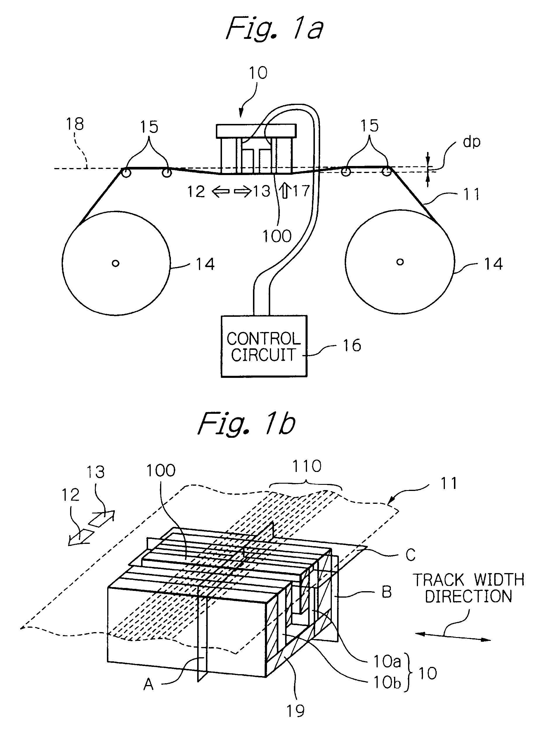
[0036]FIG. 1a shows a schematic view illustrating the main part of one embodiment of the magnetic tape apparatus according to the present invention. And FIG. 1b shows a perspective view schematically illustrating one mode of the configuration of the magnetic recording medium and the thin-film magnetic head according to the present invention.

[0037]As shown in FIG. 1a, the magnetic tape apparatus of the present embodiment includes: a magnetic tape 11 as a magnetic recording medium; a tape head 10 as a thin-film magnetic head for performing read and write operations to the magnetic tape 11; reels 14 for winding and unwinding (feeding) the magnetic tape 11; guide pins 15 for guiding the running of the magnetic tape 11; and a recording / reproducing and pressure control circuit 16.

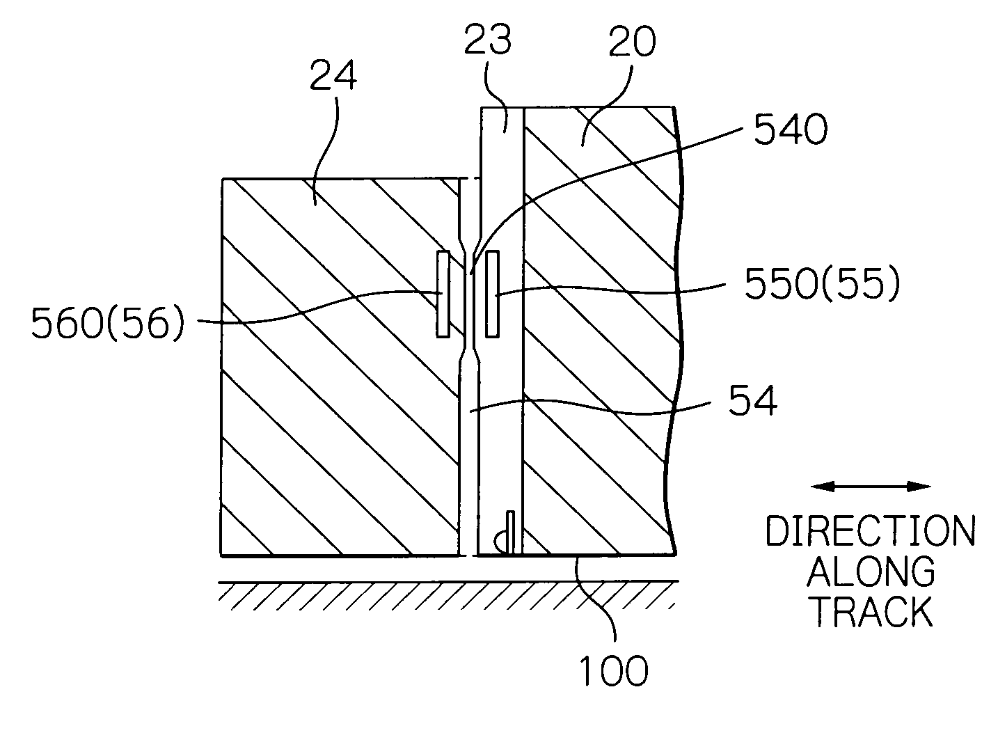
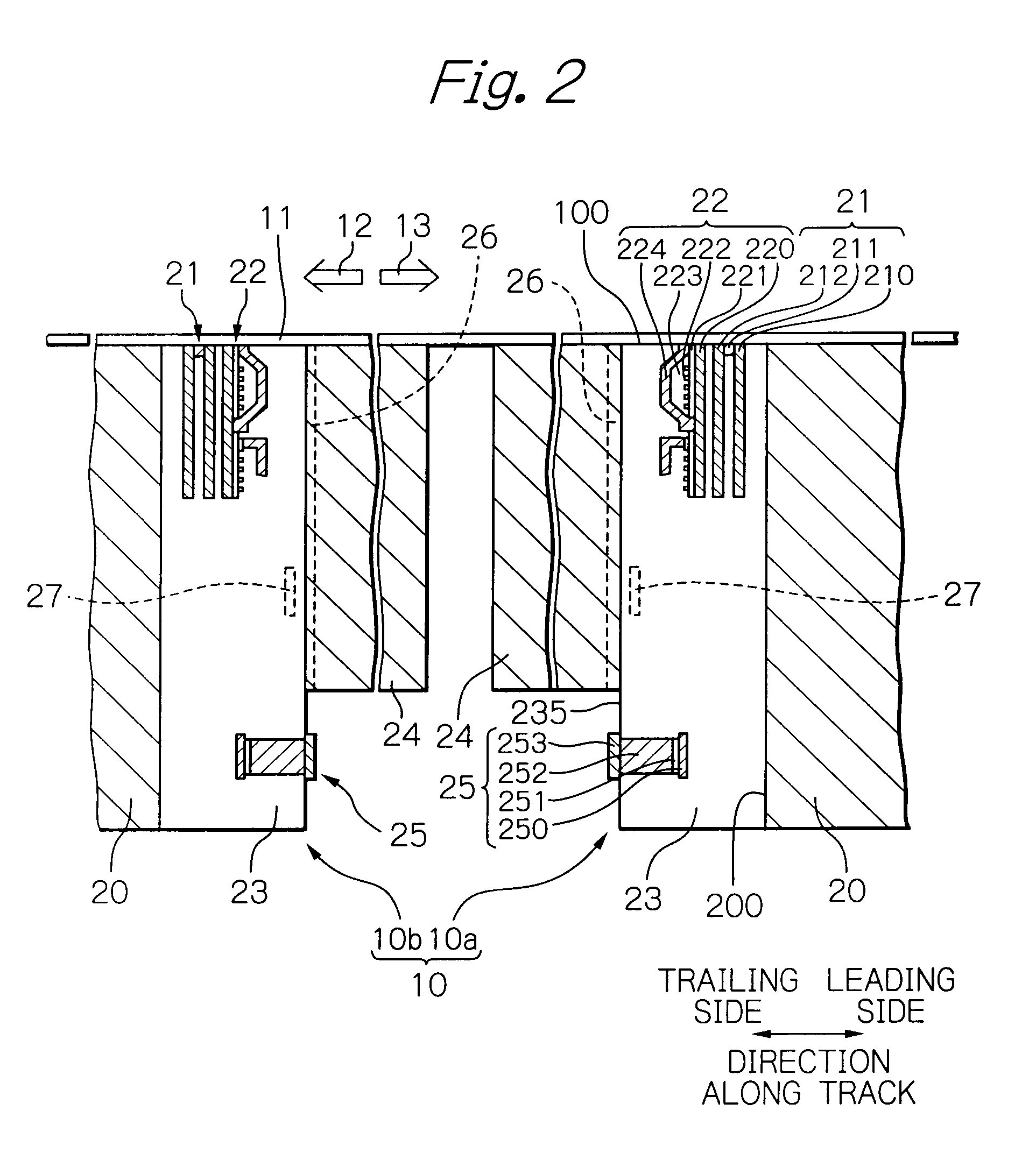
[0038]The tape head 10 is provided for reading and writing data signals, whose tape baring surface (TBS) 100, which is the end surface on the magnetic tape 11 side or a medium-opposed surface (opposed-to-medium s...


PUM

PropertyMeasurementUnit
thicknessaaaaaaaaaa
thicknessaaaaaaaaaa
thicknessaaaaaaaaaa

Abstract

Provided is a thin-film magnetic head for reading data from a magnetic recording medium and / or writing data to a magnetic recording medium, in which the magnetic spacing can be controlled appropriately by stably adjusting the pressure working between the thin-film magnetic head and the magnetic recording medium according to the change of conditions such as the change over time. This thin-film magnetic head comprises at least one through hole reaching a surface opposed to the magnetic recording medium of the thin-film magnetic head, for adjusting a pressure working between the thin-film magnetic head and the magnetic recording medium. Preferably, the head further comprises at least one flow-amount control means for controlling the flow amount of gas that flows via the at least one through hole.

Description

BACKGROUND OF THE INVENTION[0001]1. Field of the Invention[0002]The present invention relates to a thin-film magnetic head for applying to magnetic recording, especially to a tape head for reading data from a magnetic tape and writing data to the tape. The present invention further relates to a controlling method of a magnetic spacing that is a distance between the end of the magnetic head element and the surface of the recording layer of the magnetic recording medium.[0003]2. Description of the Related Art[0004]In recent years, magnetic recording and reproducing apparatuses have been remarkably improved in capacity of storage data due to the widespread use of multimedia and the Internet. And magnetic tape apparatuses for backing up or storing data are no exception of this trend of larger capacity, and have been required to be improved in a real recording density corresponding to the larger capacity.[0005]Thin-film magnetic heads are widely used, in the above-described magnetic reco...

Claims


Application Information

Patent Timeline
Patent Type & Authority Patents(United States)
IPC IPC(8): G11B5/187G11B15/64G11B21/21G11B17/32G11B5/60
CPCG11B5/00813G11B5/3106G11B5/40
Inventor HACHISUKA, NOZOMUOHTA, NAOKI
Owner TDK CORPARATION
Why Eureka
Try Eureka