Filling device and method for filling with viscous filling material

a filling device and filling technology, applied in the field of filling devices, can solve the problems of long production time of filled products, complex construction, and considerable amount of care and maintenance, and achieve the effects of simple manner, precise and direct construction, and easy maintenan

Inactive Publication Date: 2008-10-30
POLY CLIP SYST
View PDF26 Cites 4 Cited by
  • Summary
  • Abstract
  • Description
  • Claims
  • Application Information

AI Technical Summary

Benefits of technology

[0014]It is essentially possible to produce the supply of casing material in advance and to pull it at least partly onto the filling tube before the filling operation begins. It is then advantageous if the sensor for measuring the length of casing material drawn from the supply of casing material is disposed in the immediate vicinity of the filling tube, because this makes it possible to measure the length of casing material drawn from the supply in a particularly precise and direct manner. The sensor for measuring the length drawn from the supply of tubular casing material can be disposed in the immediate vicinity of the supply of casing material and can be embodied, for example, by a length measuring sensor fitted with a track roller.
[0015]It is likewise possible for the tubular casing material to be produced during the filling operation. It is advantageous in this context if there is provided a supply of flat web material for the casing material, and a sealing device which wraps the flat web material drawn from the supply of flat web material around the filling tube to form a tube and which seals the tube in the longitudinal direction. By this means, and with a suitably large supply of flat web material, any desired quantity of filled products can be produced without interruption. In this embodiment, there is also no necessity to remove the filling tube in order to replenish the supply of casing material.
[0016]In the embodiment of the invention just described, it is advantageous if the sensor for measuring the length of casing material drawn from the supply of casing material is disposed on a deflecting roller in the sealing device and measures the length of the flat web material drawn from the supply thereof. If the sensor is a rotary transducer, for example, the length of flat web material drawn off can be determined directly from the rotation of the deflecting roller, and hence the length of the casing material drawn from the supply of casing material can be determined indirectly. In addition, the sensor is not impaired when the supply of flat web material is being replenished.
[0017]It is also advantageous if the casing material is drawn by means of the pressurized filling material from the supply of casing material disposed on the filling tube. This avoids the need for an additional drive or a pull-off device. Such a drive or such a device requires additional machinery parts and their control.
[0018]In order to build up this pressure, it is also advantageous if a pressurizing device is connected to the shutoff valve. The level of pressure is chosen in such a way that no additional transport device for the filling material is necessary in the entire filling device according to the invention.
[0019]Depending on the embodiment, the shutoff valve can be actuated in different ways. In one preferred embodiment, it can be driven by a motor. Such a motor can be controlled in a particularly simple manner by an appropriate sensor signal. More improved control is possible if the motor of the shutoff valve is connected to the controller. By this means, it is possible to adapt the sensor signal to the motor being used.

Problems solved by technology

The filling systems used until now for viscous filling material and explained with the above example are of complicated construction, which involves a considerable amount of care and maintenance, especially in the food industry.
More specifically, only discontinuous operation is possible with the known filling device, due to the loading time of the piston metering machine, which leads to a long production time for the filled product being made.

Method used


Image

  • Filling device and method for filling with viscous filling material
  • Filling device and method for filling with viscous filling material
  • Filling device and method for filling with viscous filling material

Examples


Embodiment Construction

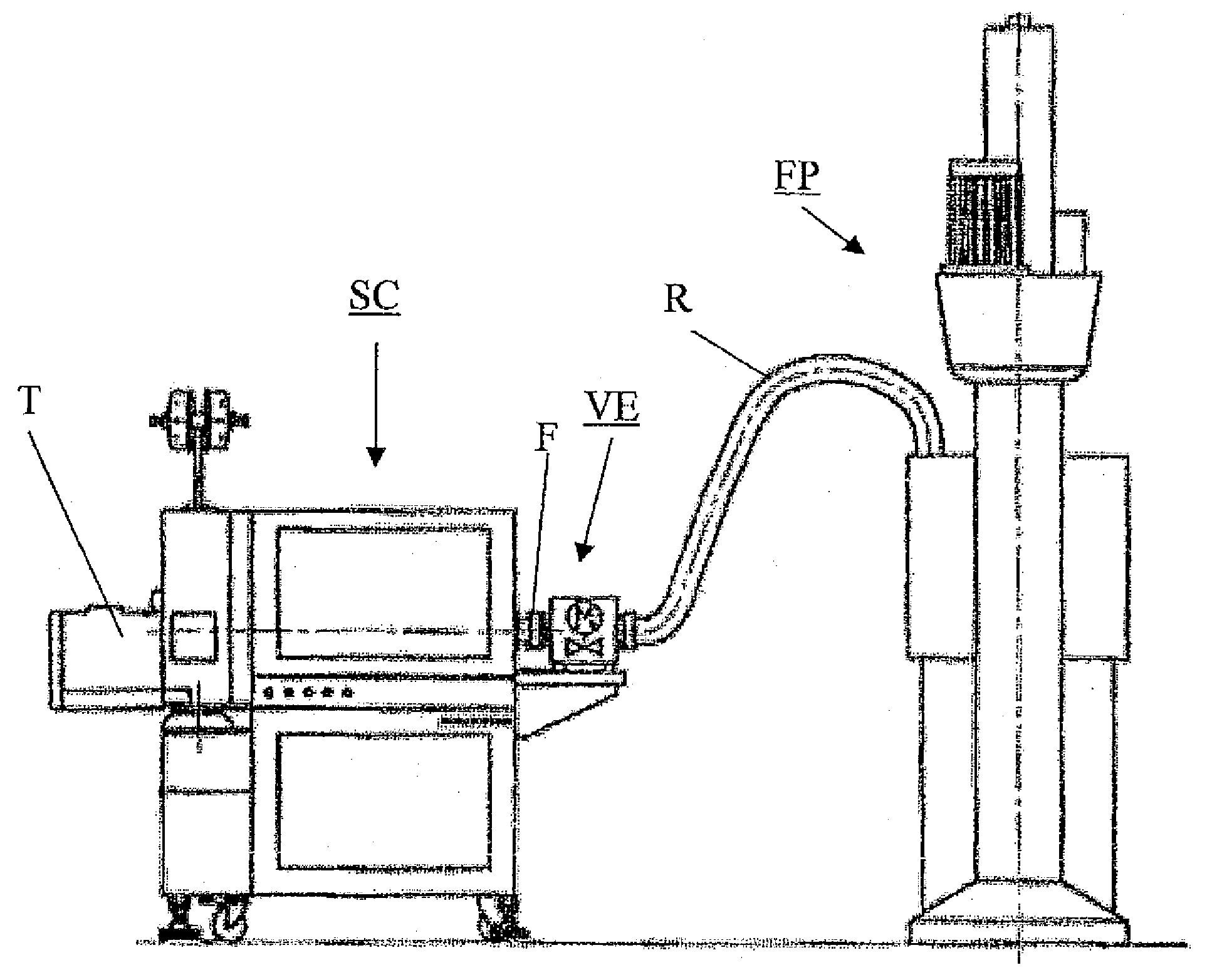
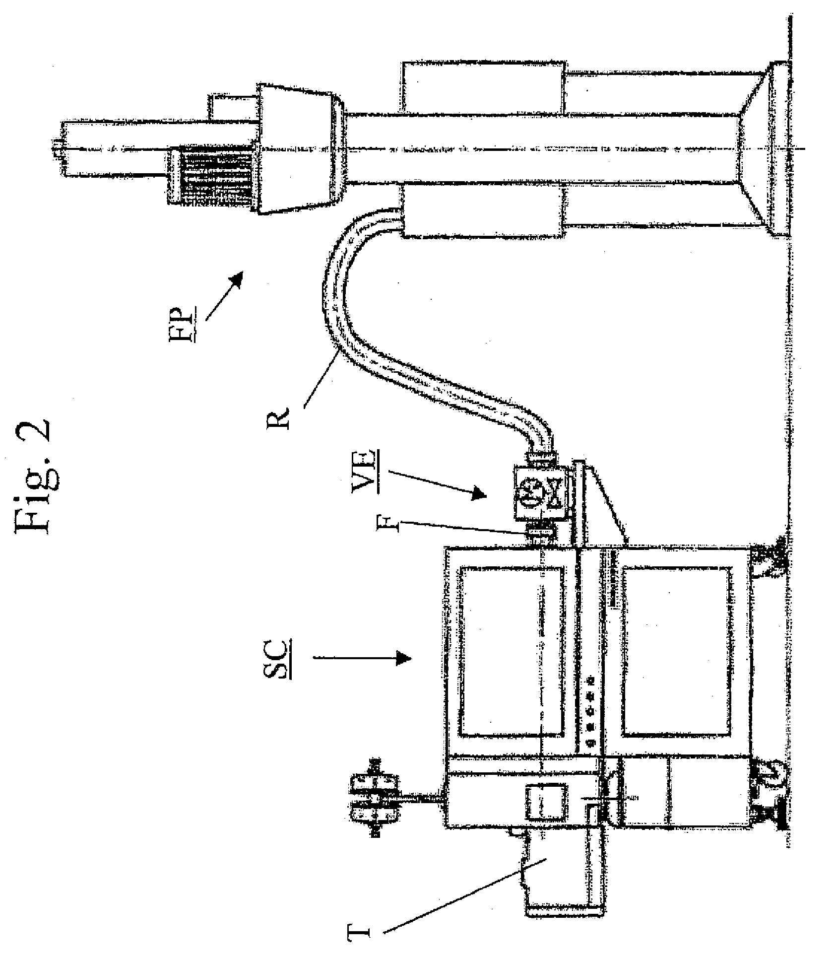
[0025]FIG. 2 shows the basic structure of a filling plant, for viscous filling material such as sealants or sausage meat, in which the filling device according to the invention is used. The filling plant comprises a known barrel press FP which is used to apply a pressure to material being conveyed. In the direction of flow of the filling material, i.e., to the left in the drawing in FIG. 2, barrel press FP is followed by valve unit VE. The connection between barrel press FP and valve unit VE is formed by a connecting hose or connecting pipe R, the latter normally consisting of a non-rusting stainless steel.

[0026]As can be seen from FIG. 3, valve unit VE comprises a shutoff valve AV and a motor M for actuating shutoff valve AV. Motor M is connected to a controller S by a signal line which is not described in any further detail, and the motor can receive control signals from the controller or send signals to it, if necessary.

[0027]Shutoff valve AV is embodied as a straight-way valve, ...


PUM

PropertyMeasurementUnit
viscousaaaaaaaaaa
lengthaaaaaaaaaa
length of timeaaaaaaaaaa

Abstract

A filling device and associated method for filling viscous filling material, in particular sealants, into a tubular casing material. The filling device comprises: a shutoff valve, a filling tube disposed downstream from the shutoff valve in the direction of flow of the filling material, a clip placement and clip closing device disposed downstream from the filling tube in the direction of flow of the filling material and a supply of tubular casing material disposed at least partially on the filling tube. At least one sensor is also provided for directly or indirectly measuring the length of casing material drawn from the supply of casing material, the output signal of the sensor being able to control at least the closing of the shutoff valve through which the pressurized filling material can be fed to the filling tube.

Description

BACKGROUND AND SUMMARY OF THE INVENTION[0001]The invention relates to a filling device for filling viscous filling material, in particular sealants, into a tubular casing material, and to a method therefor.[0002]More particularly, the invention relates to a filling device for filling viscous filling material, such as sealants, especially silicone, or sausage meat, into a tubular casing material, wherein the device comprises: a shutoff valve, a filling tube disposed downstream from the shutoff valve in the direction of flow of the filling material, a clip placement and clip closing device disposed downstream from the filling tube in the direction of flow of the filling material and a supply of tubular casing material disposed at least partially on the filling tube. The invention further relates to a method for filling viscous filling material, such as sealants, especially silicone, or sausage meat, etc., into a tubular casing material, wherein the method comprises the following steps...

Claims


Application Information

Patent Timeline
Patent Type & Authority Applications(United States)
IPC IPC(8): B65B9/10A22C11/00B65B9/073B65B9/213
CPCA22C11/0245B65B9/073B65B51/046B65B25/065B65B9/213
Inventor HANTEN, JURGEN
Owner POLY CLIP SYST
Why Eureka
Try Eureka