Tape laying apparatus and method

a technology of laying apparatus and tape, which is applied in the direction of paper hanging, mechanical control devices, instruments, etc., can solve the problems of extremely stiff unidirectional carbon fiber tape along its length, and in general is somewhat fragil

Inactive Publication Date: 2011-08-25
NORTH CUTTING SYST
View PDF9 Cites 11 Cited by
  • Summary
  • Abstract
  • Description
  • Claims
  • Application Information

AI Technical Summary

Benefits of technology

[0015]The present invention solves the above problems by mechanically separating a prior art tape head into two independent parts. Each part may be articulated independently, or one with respect to the other. The tape from a...

Problems solved by technology

Unidirectional carbon fiber tapes are extremely stiff along their length, but are...

Method used


Image

  • Tape laying apparatus and method
  • Tape laying apparatus and method
  • Tape laying apparatus and method

Examples


Embodiment Construction

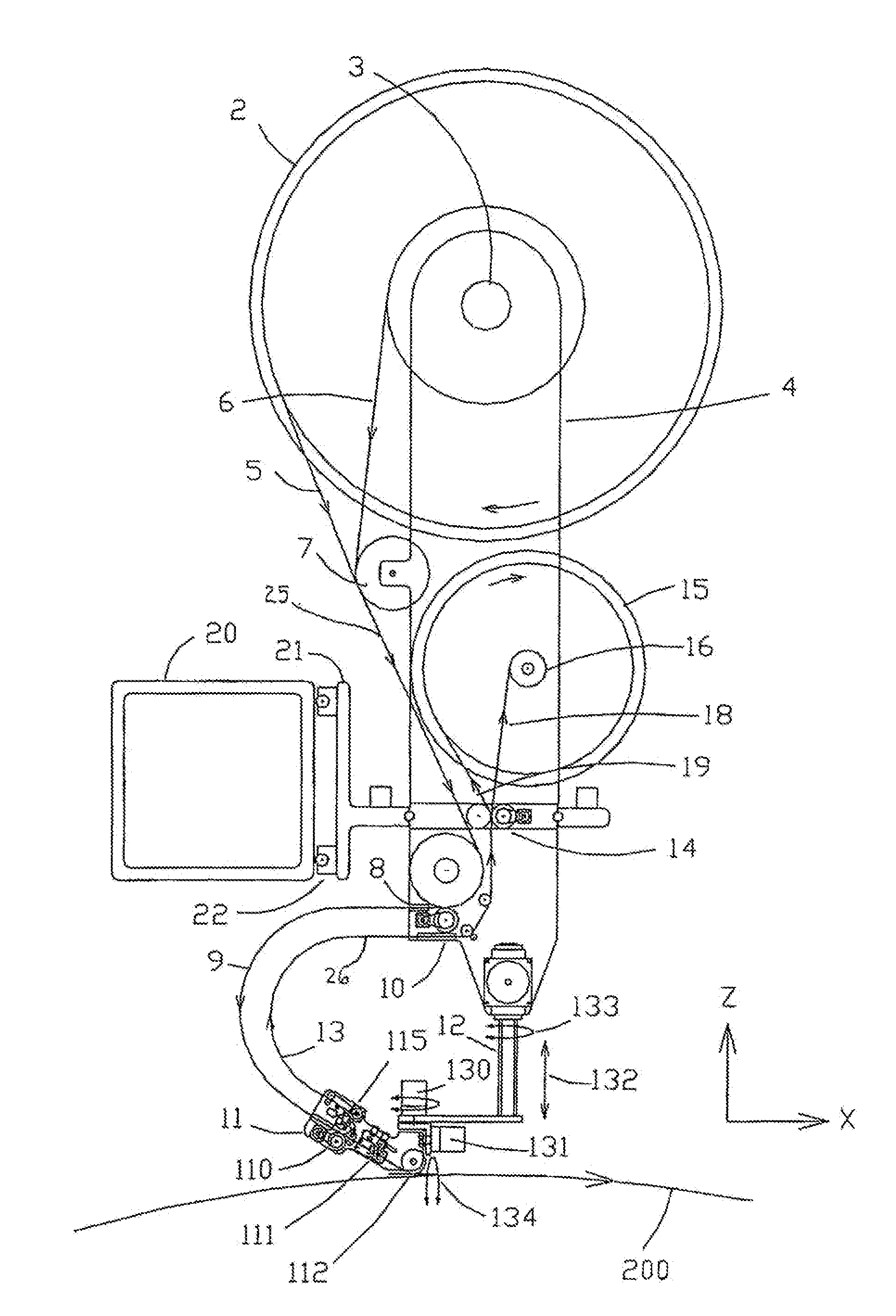
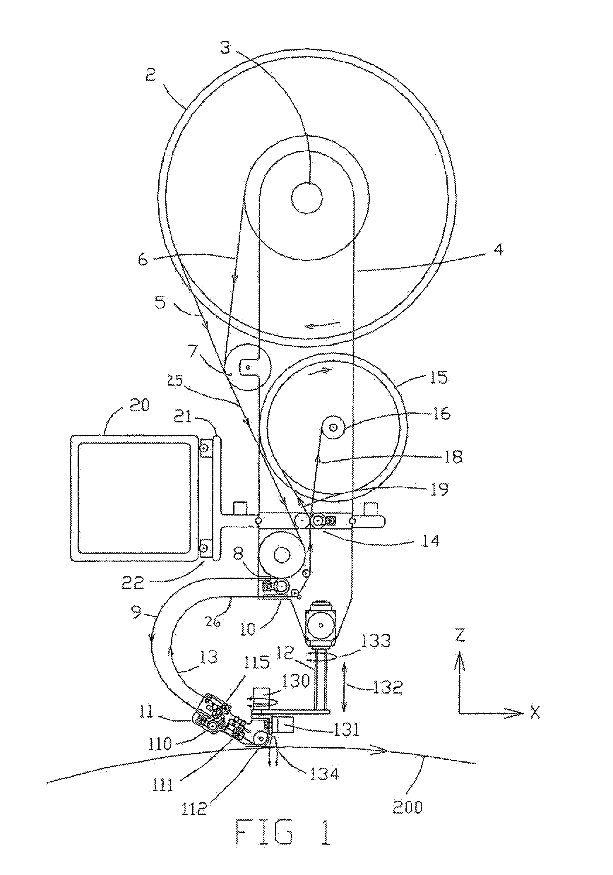
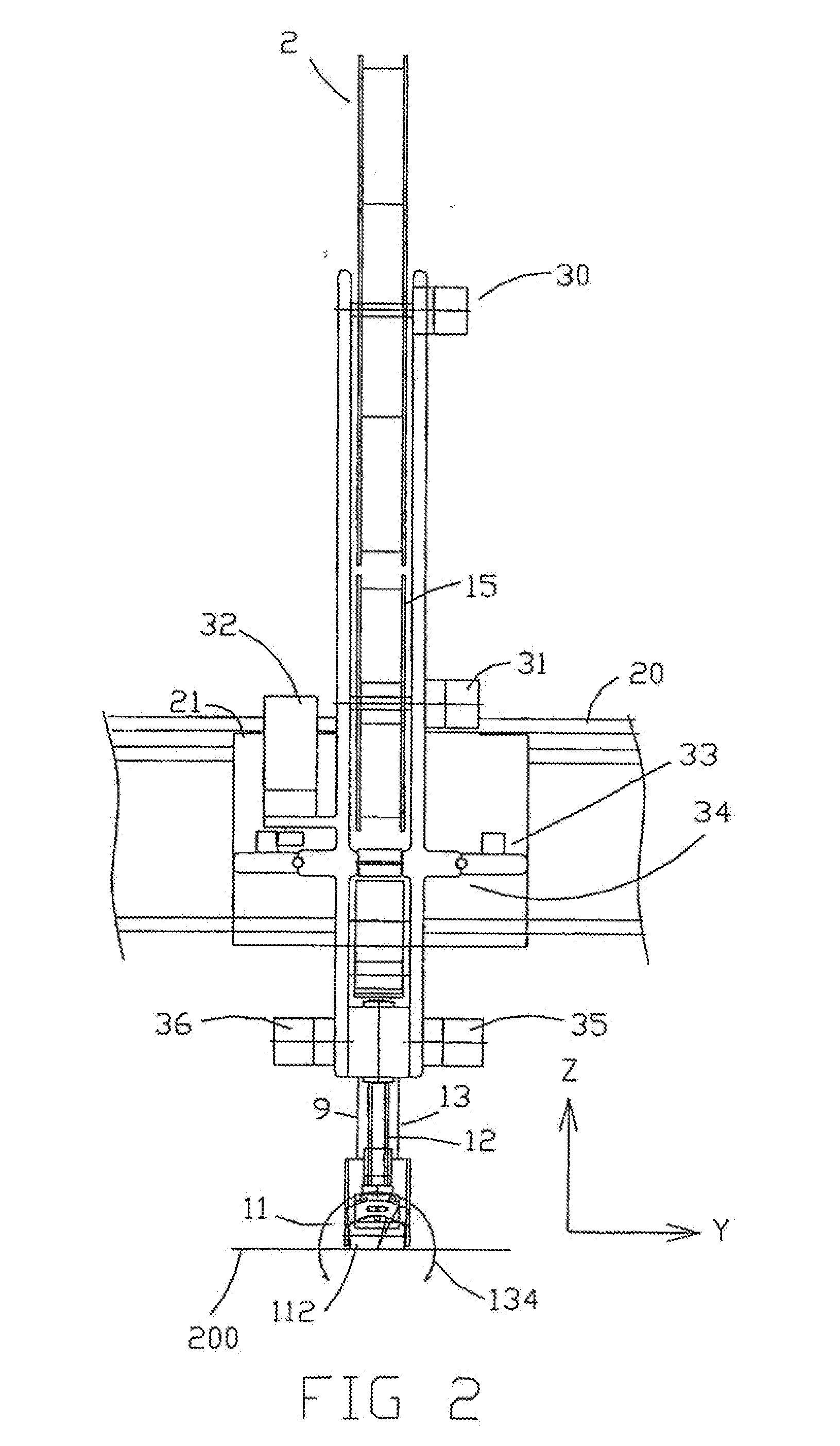
[0040]In one example, an automatic tape head assembly for a multiple axis tape laying machine for depositing tape in courses upon a work surface comprises a tape supply reel and a tape compaction roller. The tape compaction roller comprises a tape feed puller and a tape cutter. The tape supply reel and tape compaction roller are independently movable relative to the work surface and with respect to each other. The tape fed from the supply reel to the compaction roller and a tape travel path there between is maintained at substantially zero Gaussian curvature. The tape travel path between the supply reel and the compaction roller may be greater than a straight line between the supply reel and compaction roller. The tape head assembly may further comprise a backer reel rotatable around a third axis and a backer travel path between the compaction roller and the backer reel. The backer travel path may be greater than a straight line between the compaction roller and the backer reel. The...


PUM

PropertyMeasurementUnit
Lengthaaaaaaaaaa
Flexibilityaaaaaaaaaa

Abstract

An automated tape head assembly for a multiple axis tape laying machine includes a tape supply reel and a tape compaction roller, and a chute. Tape passes from the supply reel, through the chute, to the tape compaction roller. The tape path and at least a portion of the chute are maintained substantially at a zero Gaussian curvature. The tape path and chute are curved to define a compliance loop that results from a substantially or partially unrestrained curved path between the supply reel and the compaction roller. This structure allows the compaction roller to shift laterally and vertically with respect to the supply reel while the supply reel is in a fixed position with respect to the tape head assembly generally. This structure also allows the compaction roller to roll, steer, and follow the fiber tape's natural path, all with significant independence from the supply reel.

Description

[0001]This present application is a Continuation-In-Part of U.S. application Ser. No. 11 / 570,516, which was filed on Oct. 14, 2008. U.S. application Ser. No. 11 / 570,516 relies for priority on International Patent Application No. PCT / IB2005 / 004184, filed on Jun. 10, 2005 and on U.S. Provisional Patent Application Ser. No. 60 / 581,948, filed on Jun. 22, 2004. The contents of all three patent applications are incorporated herein by reference. It is noted that U.S. patent application Ser. No. 11 / 570,516 will issue as U.S. Pat. No. 7,836,931 on Nov. 23, 2010.FIELD OF THE INVENTION[0002]This application relates generally to machines that utilize a tape head to lay down composite strips on a surface and, more specifically to machines that utilize a single tape head or multiple tape heads simultaneously to lay fiber tape onto a contoured surface or mandrel.BACKGROUND OF THE INVENTION[0003]Because of the nature of a tape, especially a stiff fiber tape, existing tape heads maintain a tape traj...

Claims


Application Information

Patent Timeline
IPC IPC(8): B32B37/20
CPCB29C70/388B29C70/545Y10T156/1788Y10T156/1795Y10T156/1348
Inventor SLYNE, WILLIAM J.
Owner NORTH CUTTING SYST
Why Eureka
Try Eureka