Fuel Cell System

a fuel cell and system technology, applied in the field of fuel cell systems, can solve the problems of insufficient heat recovery of fuel, inability to quickly reform fuel, and inability to provide solid-oxide fuel cell systems, etc., and achieve the effect of stably providing to a load

Active Publication Date: 2009-12-03
KYOCERA CORP
View PDF3 Cites 8 Cited by
  • Summary
  • Abstract
  • Description
  • Claims
  • Application Information

AI Technical Summary

Benefits of technology

[0014]The fuel cell system has a controller that controls the supply amount of fuel gas in accordance with the amount of hot water supplied to the user to thereby change the fuel utilization ratio by the fuel cell. For example, in the case where a large amount of hot water is required or when the ratio of hot water in the hot water storage tank is small, the fuel utilization ratio is lowered irrespective of the level of the electrical load. Thereby, the energy amount of the 
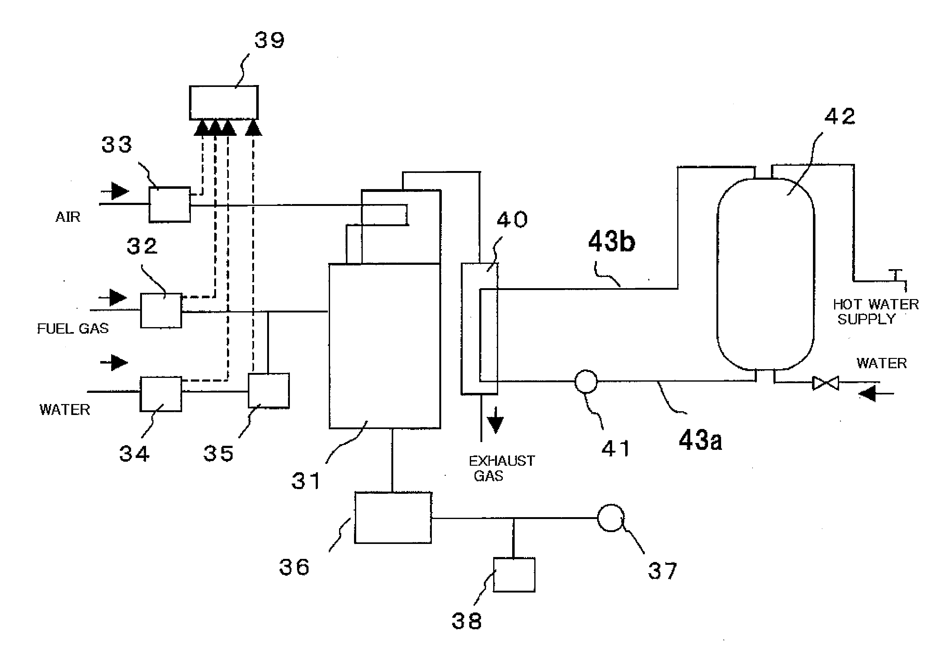
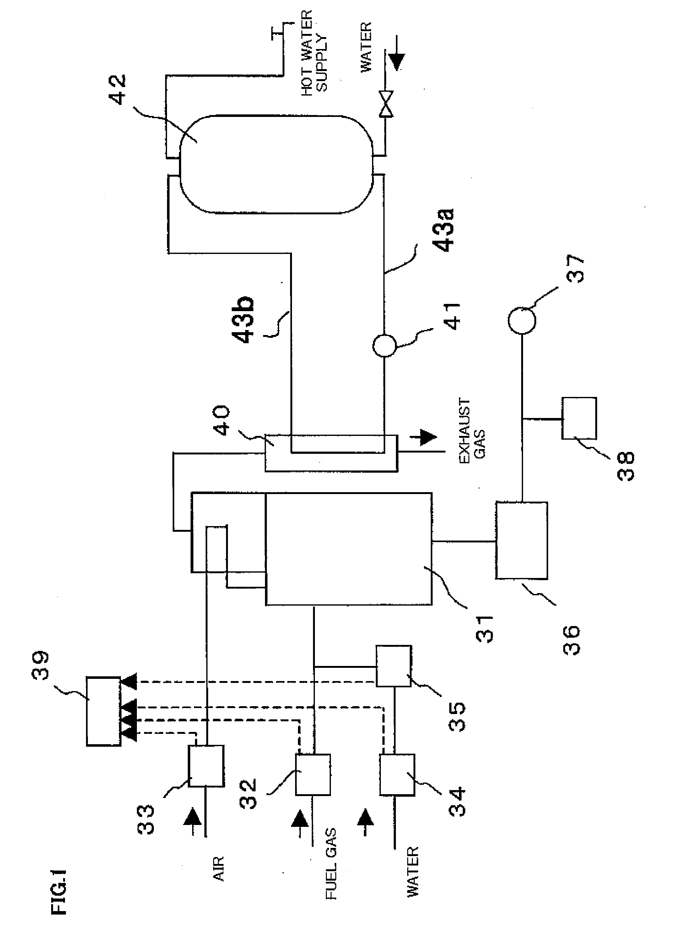
exhaust gas generated by the fuel cell is increased; and thus, the amount of hot water generated by the heat exchanger is increased. As a result, the storage amount (ratio of hot water in the hot water storage tank) or temperature of the hot water is increased. Consequently, the amount of hot water is increased and hot water can be stably supplied to the load.
[0017]Conventionally, there was the following problem. That is, when such a state continuously occurs that the power generation amount decreases and the operation temperature of the fuel cell decreases, the amount of heat recovered from the exhaust heat decreases and the amount of hot water to be supplied to the load also decreases. Accompanying this, when the operation temperature of the fuel cell decreases, the power generation efficiency of the fuel cell decreases. As a result, the maximum power amount suppliable to the electrical load decreases lower than a rating. After that, it takes a considerable long time for the fuel cell to recover the operation temperature again up to a level so that the maximum power amount suppliable to the electrical load generated by the fuel cell reaches the rating and the power generation efficiency is satisfactorily high. As a result, the fuel cell fails to satisfy a sharply increased need for the power of the load. In contrast, according to the present invention, when the operation temperature of the fuel cell decreases, the amount of the fuel gas supplied to the fuel cell is increased and combusted. Thereby, the fuel utilization ratio is reduced and the temperature of the exhaust gas is increased. The heat exchange between the exhaust gas and the water by the heat exchanger is accelerated and the generation amount of hot water is increased, and thus the ratio of the hot water in the hot water storage tank is increased. Furthermore, the water temperature in the hot water storage tank can be raised in a short time, and the operation temperature of the fuel cell is prevented from decreasing largely. Furthermore, the temperature of the fuel cell can be raised in a short time to a temperature at which the maximum power supply can be supplied to the electrical load. Thus, the required power can be swiftly supplied to the load.
[0018]Also, when power generation amount of the solid-oxide fuel cell decreases, the controller controls to reduce the fuel utilization ratio of the solid-oxide fuel cell.
[0019]When the power amount generated by the fuel cell decreases, the amount of fuel gas supplied to the fuel cell is increased to thereby reduce the fuel utilization ratio. Consequently, the operation temperature of the fuel cell is prevented from decreasing largely. Thus, the fuel cell can swiftly supply the required power. In this case also, since the amount of exhaust heat increases, the generation amount of hot water can be increased and the storage amount of hot water can be increased.
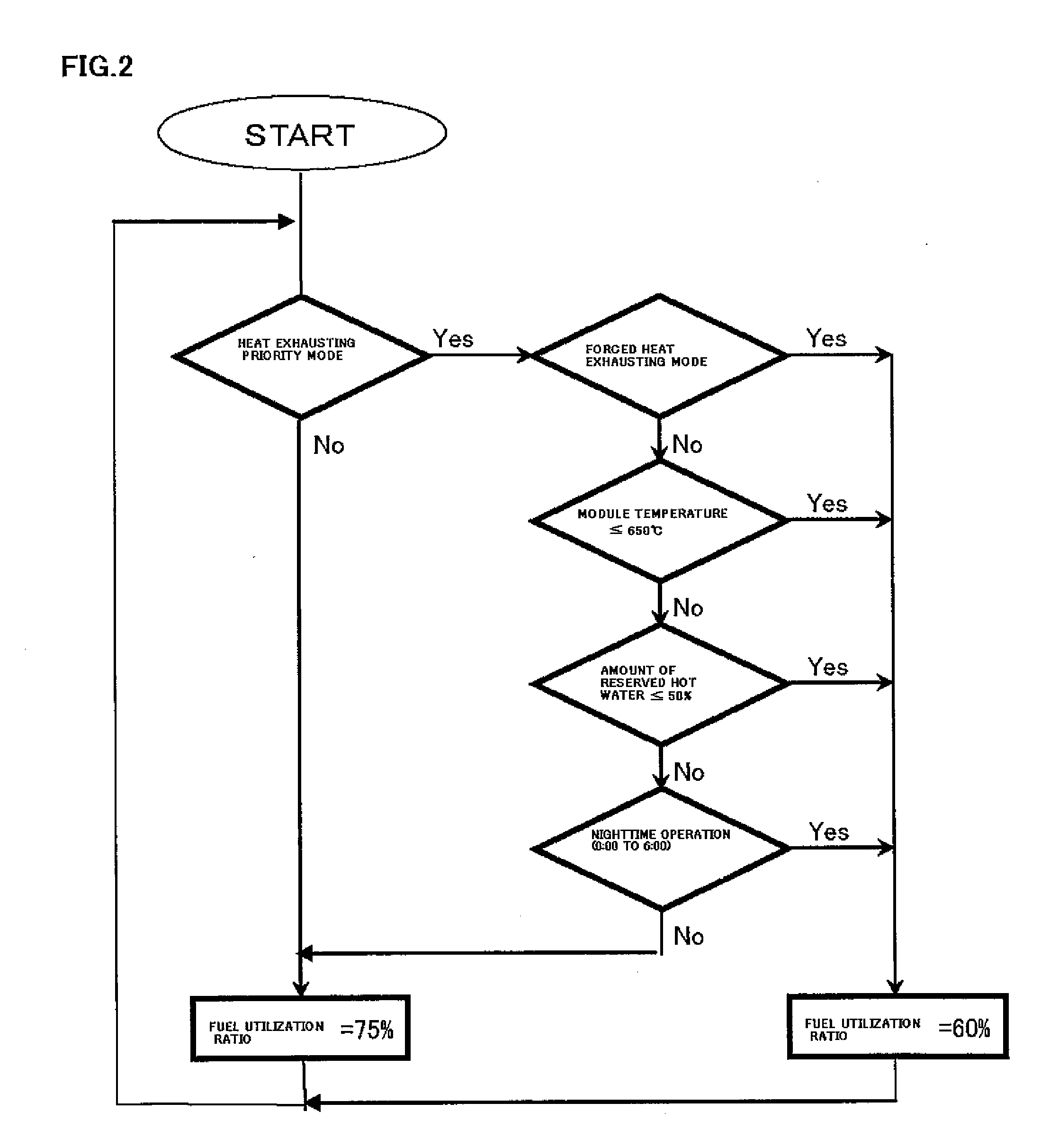
[0020]Further, the controller controls to reduce the fuel utilization ratio of the solid-oxide fuel cell during the night.
[0021]During the night, in many cases, the load in an ordinary home reaches a minimum used amount of hot water causing a decrease of the operation temperature of the fuel cell. In this case, by controlling to reduce the fuel utilization ratio of the fuel cell, the operation temperature of the fuel cell is prevented from decreasing. Thus, the required power can be swiftly supplied to the load as well as the generation amount of hot water can be increased.

Problems solved by technology

Although the generated carbon monoxide is removed, there is a problem that considerable time is required to remove the carbon monoxide.
Therefore, the fuel is hardly reformed swiftly corresponding to the power generation amount and / or temperature changes.
However, no exhaust heat recovery system has been proposed for a solid-oxide fuel cell system.
Since an electrolyte is different from a solid electrolyte, the control relevant to the exhaust heat recovery for the polymer electrolyte fuel cell system cannot be applied to the solid-oxide fuel cell system as is.
However, in view of stable supply of hot water to a load to be supplied therewith, the solid-oxide fuel cell has a disadvantage that the absolute suppliable amount of hot water is small.

Method used


Image

  • Fuel Cell System
  • Fuel Cell System
  • Fuel Cell System

Examples


Embodiment Construction

[0028]The best mode for carrying out the invention will be described below with reference to the drawings. It should be noted that the following description is intended to give an example of the best mode of the invention only. It is easy for a so-called person skilled in the art to modify or alter a part of the invention into another embodiment within the sprit of the invention. Therefore, the following description is not intended to limit the scope of the claims of the invention.

[0029]FIG. 1 shows a fuel cell system according to the invention. As illustrated in FIG. 1, a fuel cell system of a solid-oxide fuel type of the invention includes a solid-oxide fuel cell 31, a fuel supply device 32 that supplies city gas, natural gas or the like to the fuel cell 31, an air supply device 33 that supplies air as an oxidizing agent to the fuel cell 31, a water supply device 34 that supplies water, and a fuel humidifying device 35 that humidifies a fuel gas supplied to the fuel cell 31. A con...


PUM

PropertyMeasurementUnit
poweraaaaaaaaaa
poweraaaaaaaaaa
temperatureaaaaaaaaaa

Abstract

A fuel cell system capable of stably supplying hot water to a load is provided.The fuel cell system includes a solid-oxide fuel cell 31, a heat exchanger 40 that exchanges heat between an exhaust gas from the solid-oxide fuel cell 31 and water, a hot water storage tank 42 that reserves the water, circulation pipes 43a and 43b for circulating the water between the hot water storage tank 42 and the heat exchanger 40, and a circulation pump 41 provided to the circulation pipes 43a and 43b. The fuel cell system is provided with a controller 39 that controls the fuel utilization ratio during power generation by the solid-oxide fuel cell 31 in accordance with the used amount of reserved hot water.

Description

BACKGROUND OF THE INVENTION[0001]1. Field of the Invention[0002]The present invention relates to a fuel cell system utilizing a solid-oxide fuel cell, in particular to a fuel cell system capable of variably controlling the fuel utilization ratio.[0003]2. Description of the Related Art[0004]A control method of a conventional polymer electrolyte fuel cell system is described. FIG. 3 shows a conventional polymer electrolyte fuel cell system. As illustrated in FIG. 3, when the fuel cell system is operated, a fuel processing device 14 reforms a material such as natural gas using steam to generate a gas containing hydrogen as a main component. The gas is humidified by a hydrogen-side humidifier 11 and supplied to a fuel cell 1. Also, an air-supply device 3 supplies air as an oxidation gas to an oxidation-side humidifier 13, and the oxidation gas is humidified thereby and supplied to the fuel cell 1. The fuel cell 1 is connected to a power conditioner 6 that converts generated DC power to ...

Claims


Application Information

Patent Timeline
Patent Type & Authority Applications(United States)
IPC IPC(8): H01M8/04
CPCH01M8/04029H01M8/04059H01M8/04298H01M8/04358H01M8/04798Y02B90/16H01M2008/1293H01M2250/405Y02E60/521Y02E60/525H01M8/12Y02B90/10Y02E60/50
Inventor HIGUCHI, TANEO
Owner KYOCERA CORP
Why Eureka
Try Eureka