Catalytic reactor cartridge

a technology of catalytic reactor and cartridge, which is applied in the direction of combustion type, physical/chemical process catalyst, combustion using catalytic materials, etc., to achieve the effect of enhancing heat transfer

Inactive Publication Date: 2006-10-19
CATACEL
View PDF24 Cites 27 Cited by
  • Summary
  • Abstract
  • Description
  • Claims
  • Application Information

AI Technical Summary

Benefits of technology

[0006] In one preferred embodiment, the present invention comprises a cartridge having a plurality of spaced-apart monoliths, each monolith defining channels for gas flow, each monolith imparting a swirl to gases flowing through the channels. Adjacent monoliths impart swirls that have different directions. In particular, the direction of swirl of the gas is reversed from one monolith to the next. This reversal causes turbulence in the mixing areas between monoliths, and enhances heat transfer between the exterior and the interior of the monoliths.
[0007] The monoliths are preferably formed of pairs of flat and corrugated metal strips, the strips being wound around a mandrel, such as a tube or rod, to define a spiral structure. Each corrugated strip has corrugations that are oblique to the longitudinal axis of the strip. The oblique orientation of the corrugations is what imparts the swirl to the gases. The spaces between monoliths comprise mixing areas for gas. Retainers may be inserted in these spaces, to help maintain the spacing and to prevent telescoping of the layers of the monoliths, due to pressure of the gas stream. The strips may be conventional metal foil strips, or they may be made of a fine-pitch screen, to allow additional mixing and heat transfer by radiation.
[0011] The present invention therefore has the primary object of providing a reactor cartridge that can be used in catalytic or non-catalytic combustion, or for catalytic reforming, or for other endothermic or exothermic catalytic reactions, or for simple heat exchange.
[0013] The invention has the further object of providing a reactor cartridge which promotes rapid heat transfer throughout the cartridge, and which avoids the problems associated with the use of a packed ceramic bed.

Problems solved by technology

This reversal causes turbulence in the mixing areas between monoliths, and enhances heat transfer between the exterior and the interior of the monoliths.

Method used


Image

  • Catalytic reactor cartridge
  • Catalytic reactor cartridge
  • Catalytic reactor cartridge

Examples


Embodiment Construction

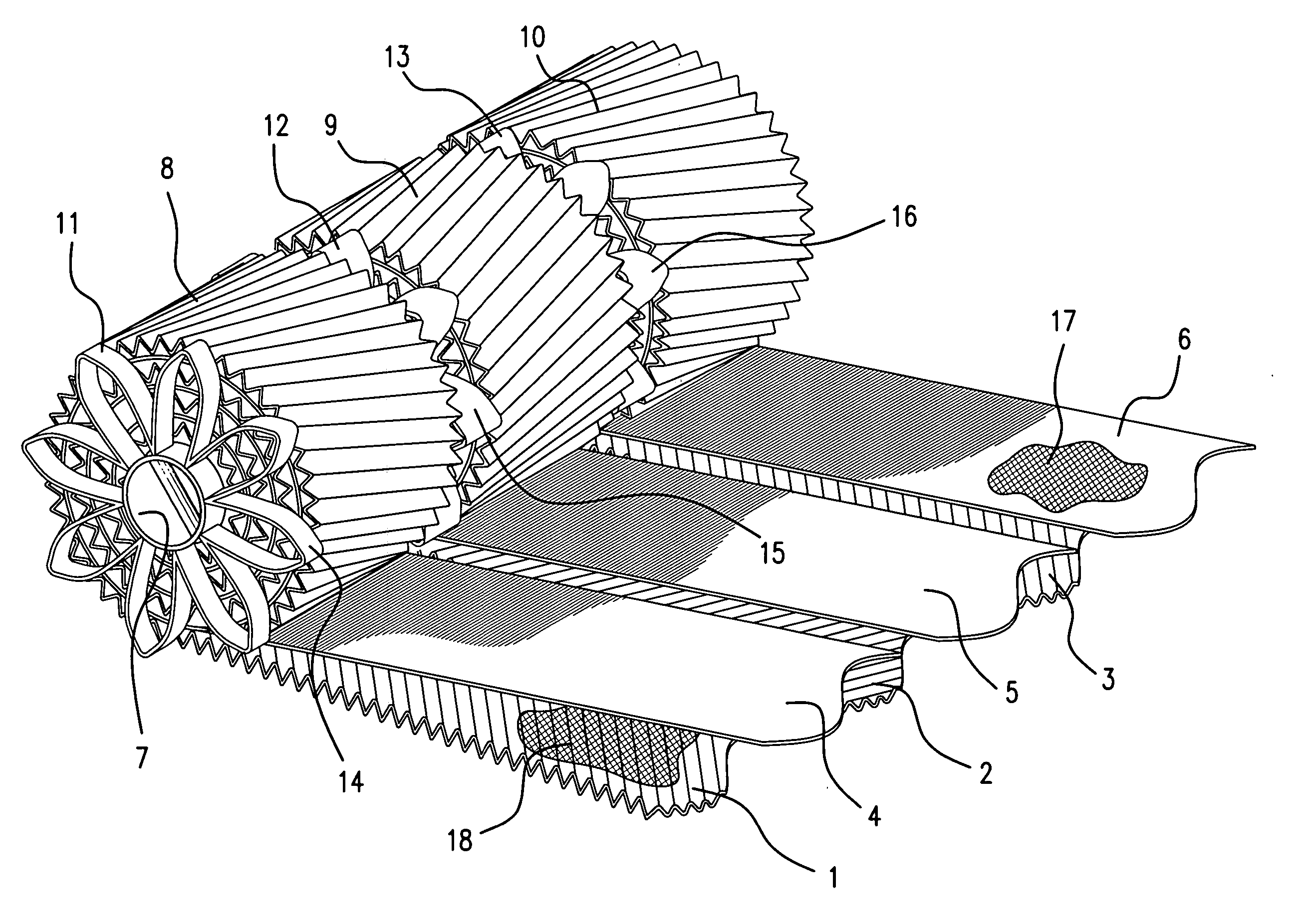
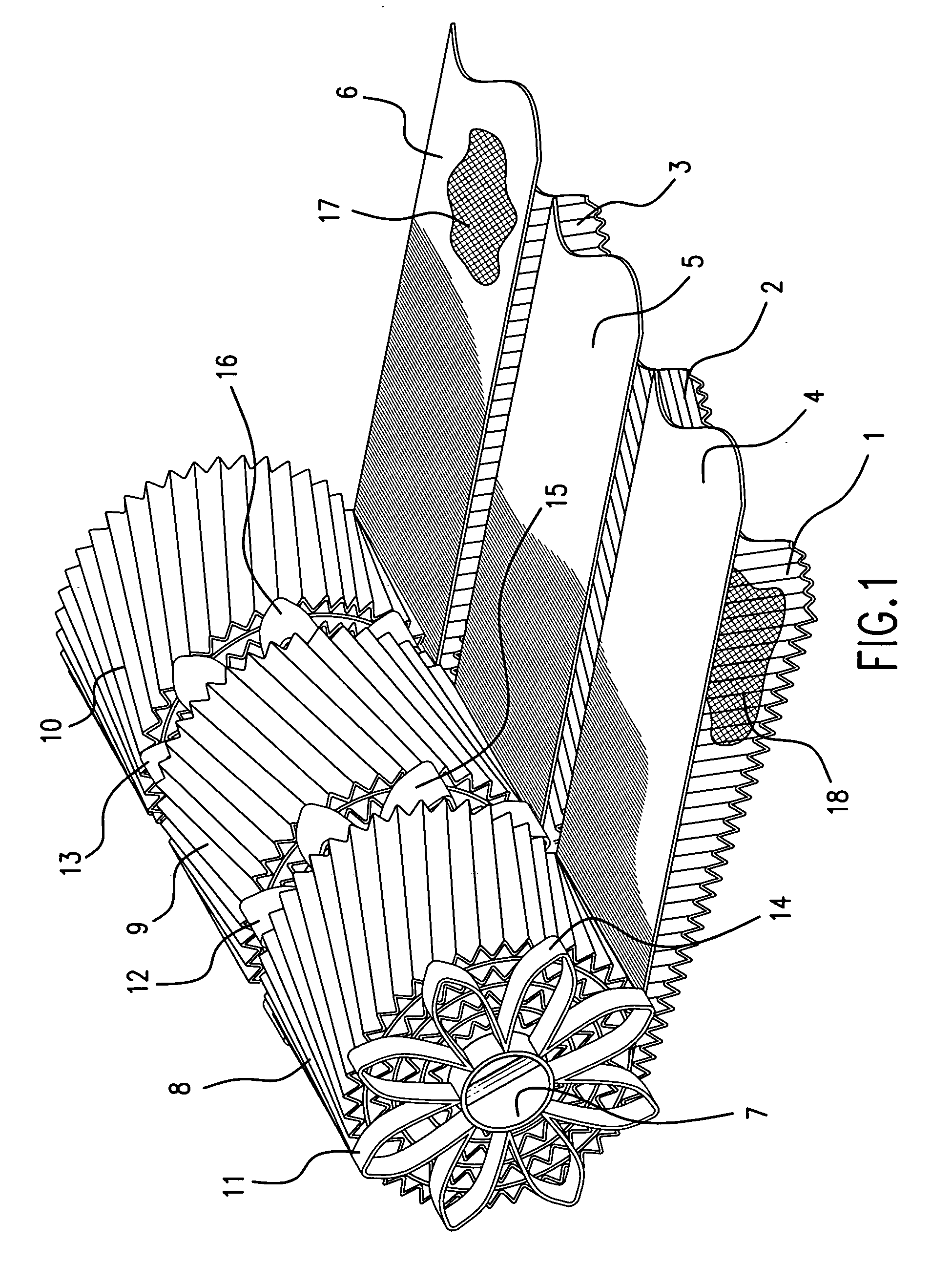
[0026]FIG. 1 illustrates the basic structure, and method of manufacture, of the reactor cartridge of the present invention. The cartridge is made from a plurality of corrugated strips 1, 2, 3 and a plurality of flat strips 4, 5, 6. The corrugated strips have skew corrugations, i.e. their corrugations are oblique relative to the longitudinal axis of the strip. The strips, which are preferably made of metal foil, are welded to, and wound around, tube 7, so as to produce three monoliths, designated by reference numerals 8, 9, and 10. The monoliths are also called “honeycombs”, because they present a multiplicity of channels to gases flowing generally axially therethrough. Each of the above channels is defined by a portion of a flat strip and a portion of an adjacent corrugated strip.

[0027] Before assembly, the corrugated strips are oriented such that the corrugations of adjacent strips are non-parallel. This orientation is achieved simply by reversing the orientation of every other co...


PUM

PropertyMeasurementUnit
sizeaaaaaaaaaa
diameteraaaaaaaaaa
axial lengthaaaaaaaaaa

Abstract

A reactor cartridge includes a plurality of spaced-apart monoliths, formed along a tube or other mandrel. Each monolith is formed of a pair of flat and corrugated metal strips, spirally wound around the tube. These strips could be made of solid or screen material. The corrugations are skewed, such that the monolith imparts a swirl to gases flowing through it. The corrugations of the strips in adjacent monoliths are oriented differently, so that successive monoliths impart different swirls to the gases, so as to promote mixing of gases and better heat transfer from the exterior to the interior of the cartridge. An insertion and removal tool simplifies the procedure for stacking such cartridges in a long pipe, or for removing cartridges from the pipe. The all-metal construction facilitates heat transfer through the entire reactor, and avoids the problems associated with packed ceramic beds.

Description

BACKGROUND OF THE INVENTION [0001] This invention relates to the field of catalytic combustion and / or heat exchange. The present invention provides a cartridge that can be used as a heat exchanger or a catalytic or non-catalytic reactor, and which can be stacked with similar cartridges in a long tube or pipe. The invention also includes a method of moving a cartridge into or out of a pipe, and a tool for accomplishing such transfer. [0002] The cartridge of the present invention achieves the same objectives as that of the catalyst support described in copending U.S. Pat. application Ser. No. 10 / 896,302, filed Jul. 21, 2004, the disclosure of which is incorporated by reference herein. [0003] One of the objectives of the above-cited application is to avoid the problems associated with the use of ceramic materials in the manufacture and operation of catalytic reactors. Packed bed ceramic catalysts have the disadvantage that they have low thermal conductivity, making it difficult to tran...

Claims


Application Information

Patent Timeline
Patent Type & Authority Applications(United States)
IPC IPC(8): B01J8/02B01J35/02B21D33/00B21D51/16B32B37/00
CPCB01F5/0643Y10T29/301B01J19/249B01J19/30B01J19/305B01J19/32B01J19/325B01J35/04B01J2219/2454B01J2219/2458B01J2219/2459B01J2219/2461B01J2219/2474B01J2219/2479B01J2219/2485B01J2219/2496B01J2219/2498B01J2219/30223B01J2219/30292B01J2219/30408B01J2219/30475B01J2219/308B01J2219/3085B01J2219/3086B01J2219/3088B01J2219/312B01J2219/32206B01J2219/3221B01J2219/32227B01J2219/32258B01J2219/32272B01J2219/32275B01J2219/32279B01J2219/32286B01J2219/32296B01J2219/32408B01J2219/32466B01J2219/32475C01B3/38C01B3/40C01B2203/0227C01B2203/0233C01B2203/1005C01B2203/1023F23C13/00F28F13/12Y10T29/49345Y10T29/302B01J19/2485Y02P20/52B01F25/4322
Inventor WHITTENBERGER, WILLIAM A.BECKER, DAVID A.BARTOS, RANDY
Owner CATACEL
Why Eureka
Try Eureka