
Laboratory centrifuge with compressor cooling

a centrifuge and compressor technology, applied in the direction of centrifuges, etc., can solve the problems of inability to prevent the heating of samples caused by the compressor, the de-mixing rate of the centrifuge is not complete or satisfactory, and the heating of the sample is not easy to achieve. achieve the effect of facilitating a higher de-mixing rate of the centrifuged samples

Inactive Publication Date: 2011-06-30
EPPENDORF AG
View PDF7 Cites 8 Cited by
  • Summary
  • Abstract
  • Description
  • Claims
  • Application Information

AI Technical Summary

Benefits of technology

[0008]Thus it is the object of the present invention to provide laboratory centrifuges which facilitate a higher de-mixing rate of the centrifuged samples.
[0015]Surprisingly the inventors have found that the de-mixing rates of the centrifuged samples can be increased in that rotation compressors are used for active refrigeration within the laboratory centrifuge.
[0019]The rotating compressors according to the invention, thus compressors which are configured, so that the compressing element at least also performs a rotating movement in the compressor cavity help to significantly reduce vibrations of this type, since a rotating movement is always performed in the interior of the compressor, so that no dead centers are created that have to be overcome like for linear compressors.
[0023]Advantageously the rotating compressors of this type also facilitate reducing the start up currents. Up to now particular laboratory centrifuges were not for sale in some countries, like for example, the USA due to the 110 V AC power grid, since the current peaks generated by powerful reciprocating piston compressors on start up would endanger the stability of the power grids used in these countries. Alternatively, particular controls had to be provided in the laboratory centrifuges which facilitate that the compressor is only controlled, so that the start-up currents do not exceed the legally required values. The rotating compressors provided according to the invention facilitate omitting controls of this type, so that the laboratory centrifuges become simpler in configuration and thus more robust and cost effective and their sale becomes legal in the countries recited supra.
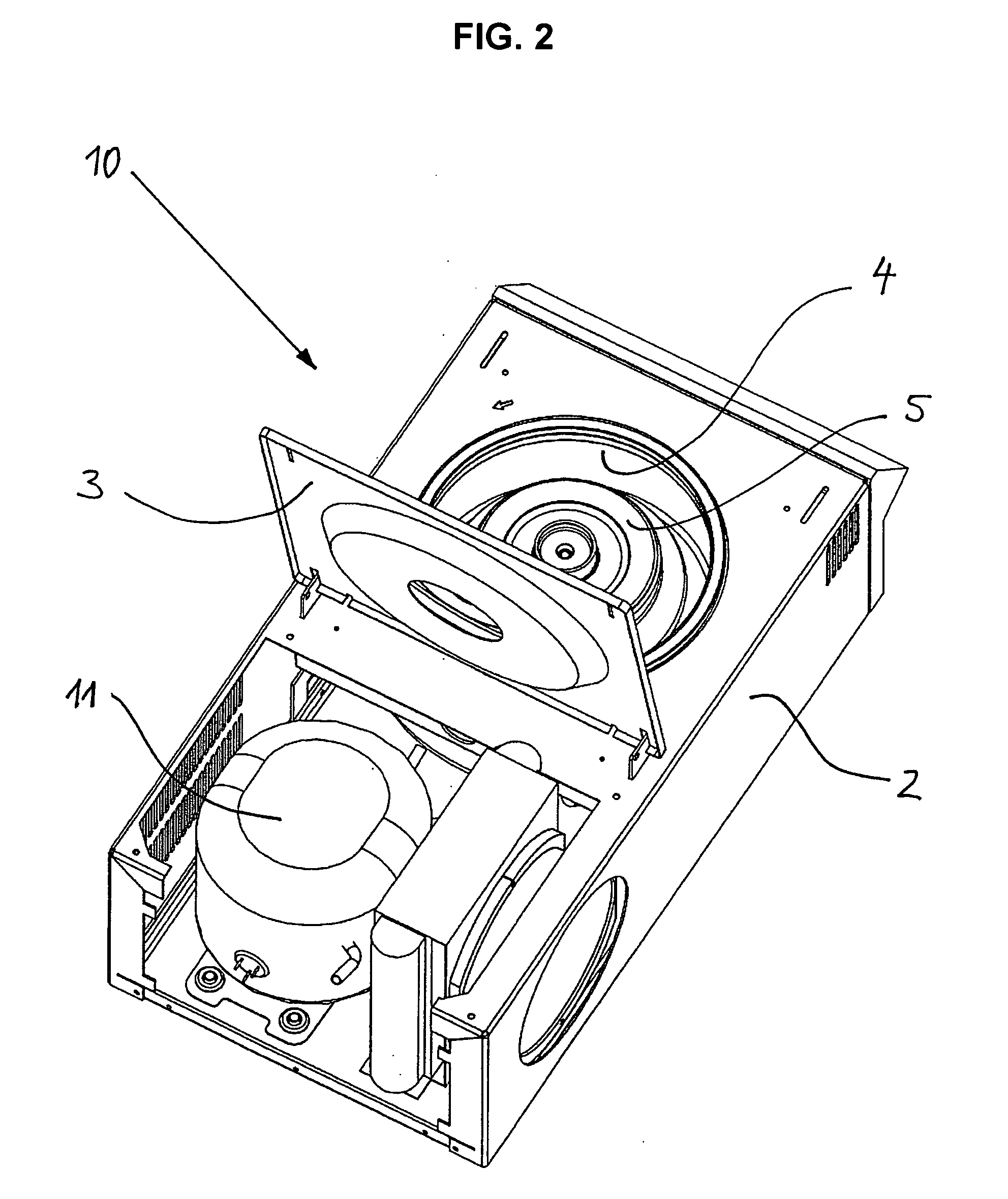
[0025]It is useful in particular when at least two compressors are disposed parallel to one another. Thus, the compressors can be configured smaller overall and with less power, so that the installation space available in a laboratory centrifuge can be used in a better manner, wherein the overall size for a laboratory centrifuge of this type is reduced.

Problems solved by technology

However, it is apparent that such centrifuges do not provide complete or satisfactory de-mixing of liquid samples.
This, however, causes a strong increase in heating since on the one hand the motor of the centrifuge rotor dissipates heat.
However, the heat is created among other things in that a fast rotation is performed under aerial drag.
The heating of samples thus caused cannot easily be prevented since a rotation under vacuum is not possible for laboratory centrifuges for cost reasons.
The heat thus created causes substantial heating of the centrifuged samples which can easily lead to their destruction or non-usability.

Method used


Image

  • Laboratory centrifuge with compressor cooling
  • Laboratory centrifuge with compressor cooling
  • Laboratory centrifuge with compressor cooling

Examples


Embodiment Construction

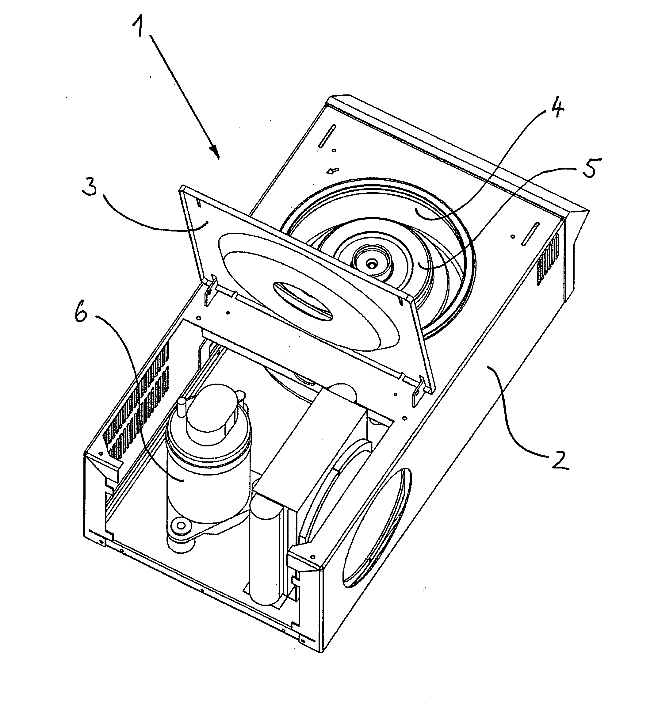
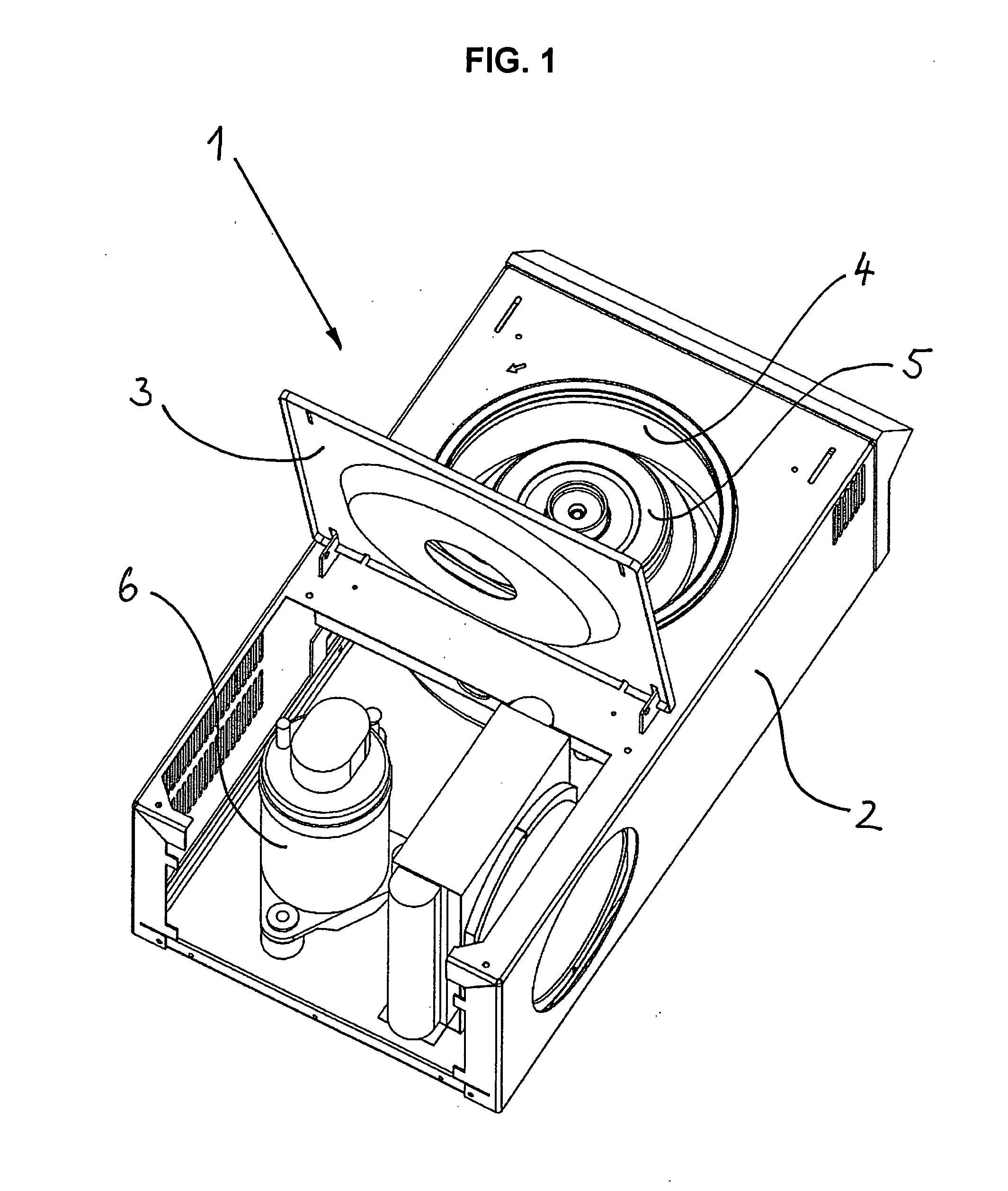
[0031]FIG. 1 schematically illustrates the laboratory centrifuge 1 according to the invention in an exemplary embodiment. The laboratory centrifuge 1 includes a housing 2 and a centrifuge cover 3. The centrifuge cover 3 is configured to close a centrifuge container 4 in which a rotor 5 is disposed. The rotor 5 is configured drivable through a motor (not shown) which facilitates centrifuging samples (not shown) disposed at the rotor 5 in order to de-mix the samples.

[0032]The laboratory centrifuge 1 includes an active cooling device for cooling the samples, wherein the cooling device includes a compressor 6. The compressor 6 is configured as a rotating compressor and includes a rolling piston compressor. The top side of the housing 2 is not illustrated in the portion of the compressor 6.

[0033]The compressor 6 is very compact and has high torque and its control is implemented through a controlled switching power supply irrespective of the grid voltage. The compressor 6 also facilitates...


PUM


Abstract

A laboratory centrifuge according to the invention provides much better de-mixing rates of centrifuged samples since providing at least one rotation compressor introduces substantially less vibration into the laboratory centrifuge, so that much lower remixing rates are provided.

Description

RELATED APPLICATIONS[0001]This application claims priority from and incorporates by reference U.S. provisional patent application 61 / 284,365, filed on Dec. 17, 2009.FIELD OF THE INVENTION[0002]The present invention relates to a laboratory centrifuge, and more particularly to a laboratory centrifuge including a rotor driven by a centrifuge motor and a cooling device including a compressor, wherein the compressor is a rotation compressor.BACKGROUND OF THE INVENTION[0003]Laboratory centrifuges of this type are being used in biological, chemical and medical labs for de-mixing various components of a liquid, or separating solids from a liquid. Thus, a centrifugal force is being used, which has different effects on different masses.[0004]In current laboratory centrifuges, typically rotational speeds of up to 16,000 revolutions per minute are generated, which generates accelerations up to 21×9.81 m / s2. However, it is apparent that such centrifuges do not provide complete or satisfactory de...

Claims


Application Information

Patent Timeline
IPC IPC(8): B04B15/02
CPCB04B15/02
Inventor HEILMANN, ANDREASMUELLER, HEIKOMARSCHNER, KAIGRIMM, BERT-OLAF
Owner EPPENDORF AG
Learn More