Fuel supply apparatus and fuel supply method for internal combustion engine

a fuel supply apparatus and internal combustion engine technology, applied in the direction of fuel injecting pumps, machines/engines, electric control, etc., can solve the problems of low pressure fuel pumps consuming electric power while the internal combustion engine is running, and achieves sufficient flow rate, suppress the generation of fuel vapor, and promote fuel gasification

Inactive Publication Date: 2011-07-07
TOYOTA JIDOSHA KK
View PDF7 Cites 33 Cited by
  • Summary
  • Abstract
  • Description
  • Claims
  • Application Information

AI Technical Summary

Benefits of technology

[0022]According to the aspect, when the engine temperature is lower than the lower limit value of the ordinary temperature region, the start-time feed pressure is set, to a high value. Therefore, it is possible to sufficiently promote gasification of the fuel, and to ensure a sufficient flow rate. Also, when the engine temperature is higher than the upper limit value of the ordinary temperature region, the start-time feed pressure is set to a high value. Therefore, it is possible to suppress generation of vapor of the fuel. The start-time setting portion may set the start-time feed pressure to a constant value when the engine temperature is in the ordinary temperature region.
[0023]As described above, in the fuel supply apparatus according to the above-described aspect of the invention, the low pressure fuel pump is controlled to avoid a discharge failure in the high pressure fuel pump. Therefore, it is possible to decrease the feed pressure to a limit value at which a discharge failure in the high pressure fuel pump can be avoided. Accordingly, the electric power consumed by the low pressure fuel pump is decreased to a limit value, without causing a discharge failure in the high pressure fuel pump. Further, in the case where a discharge failure in the high pressure fuel pump is avoided even when the feed pressure of the low pressure fuel pump is equal to the gauge pressure of...

Problems solved by technology

However, in the apparatuses, because the low pressure fuel pump is constantly operated while the internal combustion engine is...

Method used


Image

  • Fuel supply apparatus and fuel supply method for internal combustion engine
  • Fuel supply apparatus and fuel supply method for internal combustion engine
  • Fuel supply apparatus and fuel supply method for internal combustion engine

Examples


first embodiment

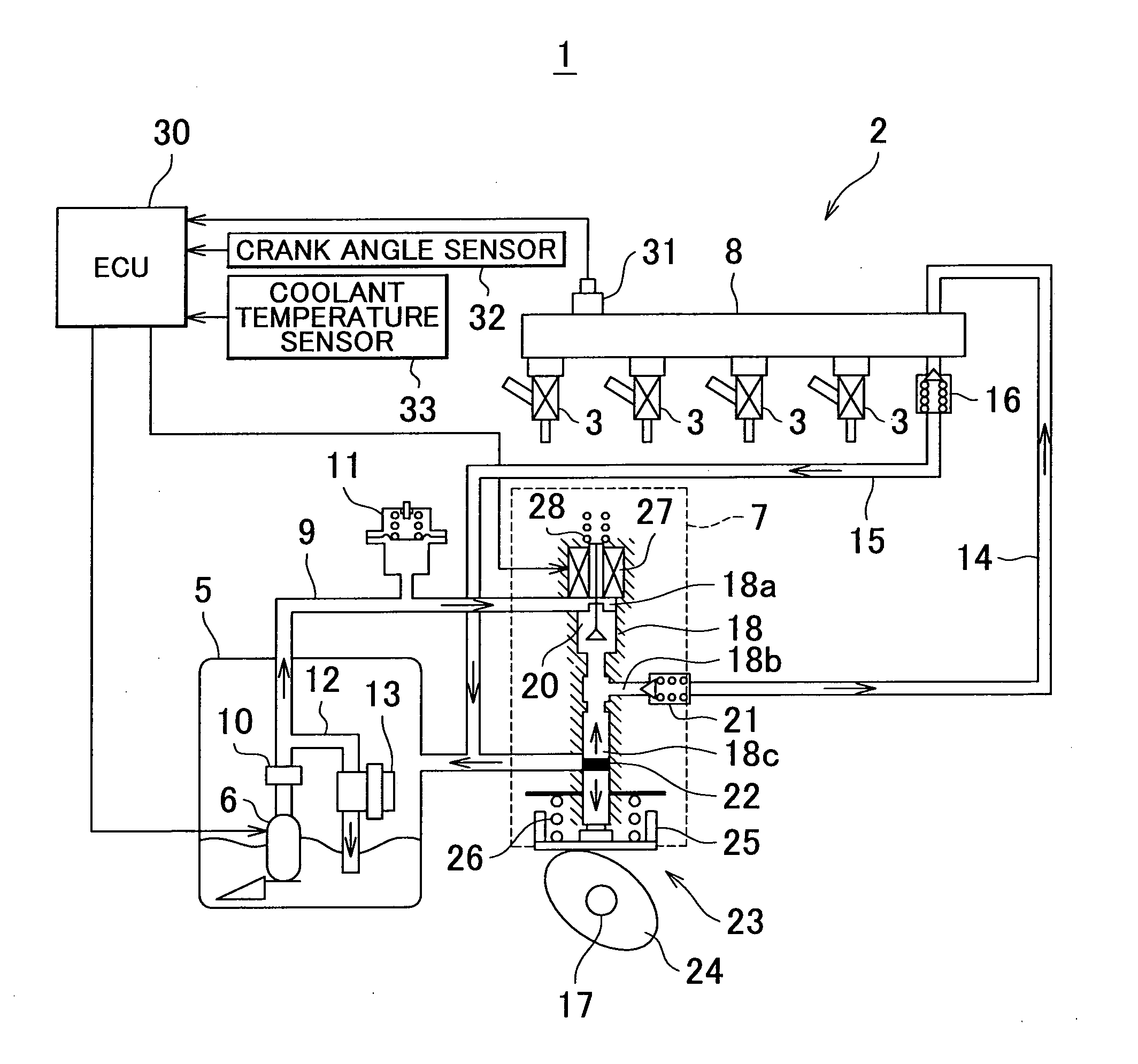
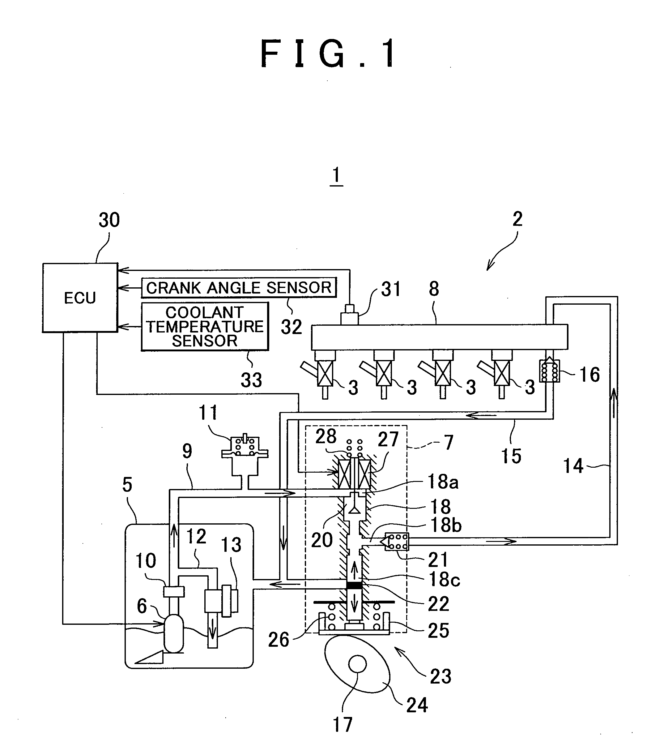
[0033]FIG. 1 is a diagram schematically showing a fuel supply system for an internal combustion engine, to which a fuel supply apparatus according to the invention is applied. An internal combustion engine 1 is provided in a vehicle (not shown) as a power source for driving the vehicle. The internal combustion engine 1 is an in-line four cylinder direct-injection spark-ignition internal combustion engine. The fuel supply apparatus 2 includes fuel injection valves 3 for respective cylinders of the internal combustion engine 1. Each fuel injection valve 3 is attached to a cylinder head (not shown) so that an end of the fuel injection valve 3 is directed into the corresponding cylinder.

[0034]The fuel supply apparatus 2 includes a low pressure fuel pump 6, a high pressure fuel pump 7, and a delivery pipe 8 so that each fuel injection valve 3 supplies fuel. The low pressure fuel pump 6 pumps up the fuel from a fuel tank 5 in which gasoline, which is the fuel, is stored. The high pressure...

third embodiment

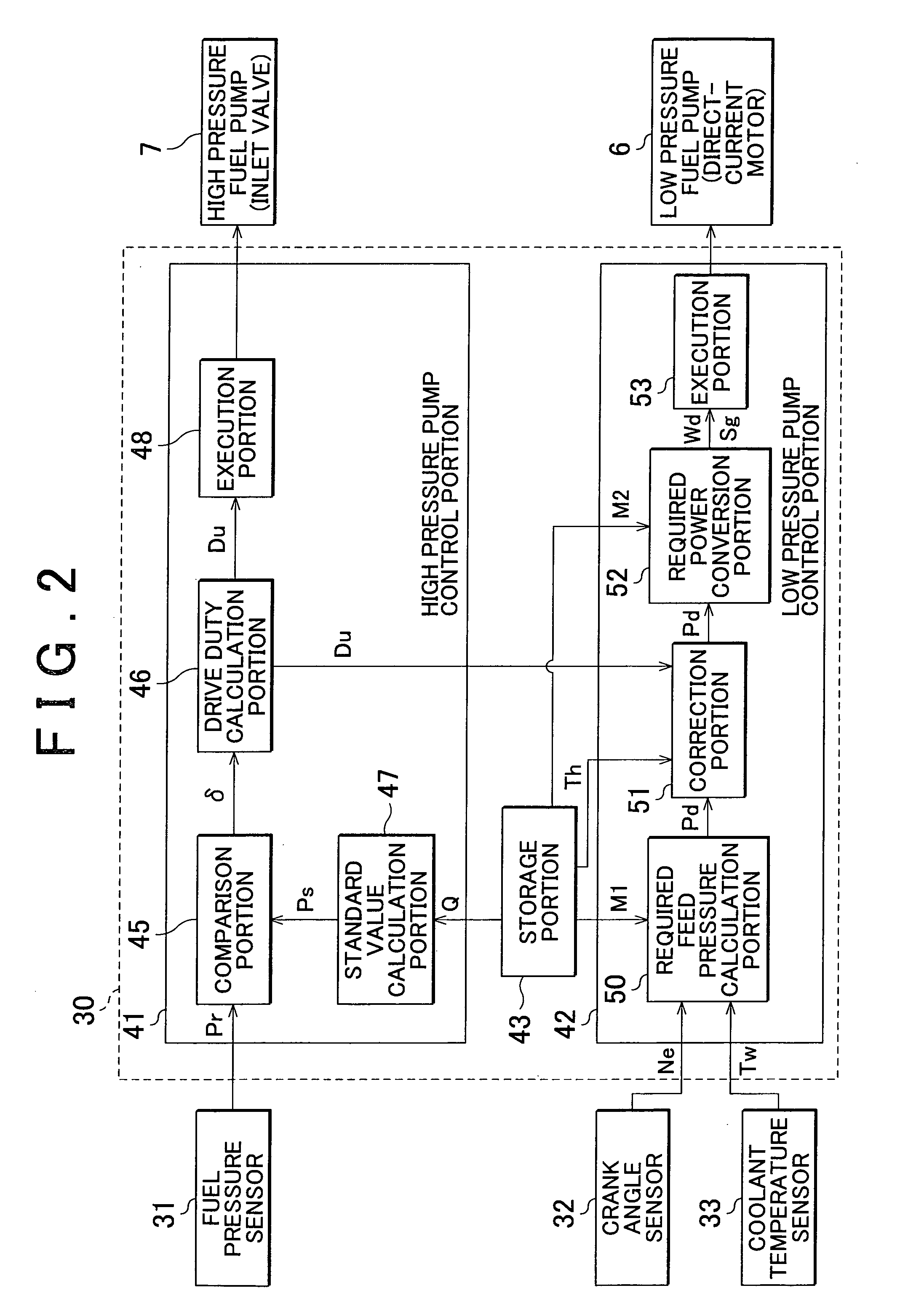
[0067]In the above-described embodiments, after the required feed pressure Pd is calculated or corrected, the pressure value is converted to the value of the electric power to be supplied to the low pressure fuel pump 6. However, the invention is not limited to the embodiments. For example, a map, in which a supplied power value that makes the feed pressure equal to the appropriate required feed pressure Pd is set using parameters such as the engine speed Ne and the coolant temperature Tw, may be prepared, and the electric power that needs to be supplied may be calculated directly based on the map, in order to omit the conversion process. This eliminates the necessity of performing the conversion process for converting the value of the pressure to the value of the electric power. Therefore, it is possible to simplify the processing in the ECU 30. The manner, in which the start-time feed pressure Pfs is treated in the third embodiment, may be similarly changed.

[0068]In the above-desc...


PUM


Abstract

In a fuel supply apparatus for an internal combustion engine, fuel is delivered to a high pressure fuel pump driven by an internal combustion engine, using an electrically-operated low pressure fuel pump, and the fuel pressurized by the high pressure fuel pump is supplied to the internal combustion engine. The fuel supply apparatus includes a low pressure pump control portion that controls the low pressure fuel pump to avoid a discharge failure in the high pressure fuel pump due to insufficiency of a feed pressure at which the low pressure fuel pump delivers the fuel to the high pressure fuel pump. The low pressure pump control portion stops the low pressure fuel pump in a case where the discharge failure in the high pressure fuel pump is avoided even when the feed pressure is equal to a gauge pressure of 0.

Description

BACKGROUND OF THE INVENTION[0001]1. Field of the Invention[0002]The invention relates to a fuel supply apparatus and a fuel supply method for an internal combustion engine, in which fuel is delivered to a high pressure fuel pump driven by an internal combustion engine, using an electrically-operated low pressure fuel pump, and the fuel pressurized by the high pressure fuel pump is supplied to the internal combustion engine.[0003]2. Description of the Related Art[0004]Japanese Patent Application Publication No. 2005-307931 (JP-A-2005-307931) describes a fuel supply apparatus for an internal combustion engine, in which a target fuel pressure is decreased to a value lower than a lower limit value of a normal range in a control of a discharge amount of a low pressure fuel pump, when a high pressure fuel pump supplies an excessive amount of the fuel. Japanese Patent Application Publication No. 11-210582 (JP-A-11-210582) describes a fuel supply apparatus in which a load of a low pressure ...

Claims


Application Information

Patent Timeline
IPC IPC(8): F02M69/54
CPCF02D41/062F02D41/2448F02D41/3082F02D41/3845F02M63/025F02D2250/31F02M37/10F02M59/366F02D2200/0602
Inventor KOJIMA, SUSUMUSUGIMOTO, TOMOJIRO
Owner TOYOTA JIDOSHA KK
Why Eureka
Try Eureka