Electronic apparatus

Inactive Publication Date: 2011-07-07
FUNAI ELECTRIC CO LTD
View PDF8 Cites 0 Cited by
  • Summary
  • Abstract
  • Description
  • Claims
  • Application Information

AI Technical Summary

Benefits of technology

[0007]An object of the present invention is to provide an electronic apparatus with high assembling efficiency.
[0009]The thus structured electronic apparatus according to the present invention makes it possible to introduce the main body-side joint member of the hinge unit into the hinge housing portion from outside the main body case (through the opening of the hinge housing portion) and to connect the main body-side joint member to the hinge connecting portion of the main body unit in a state where the upper case and the lower case of the main body case are connected to each other (i.e. a state where the main body unit is already assembled). Thus, when assembling the electronic apparatus, the hinge unit can be connected to the main body unit in a state where the main body unit is already assembled (i.e. a state where the upper case and the lower case of the main body case are already connected to each other), making it possible to achieve high assembling efficiency. In addition, the main body-side joint member of the hinge unit is housed in the hinge housing portion, which is recessed downward from its periphery in the main body case, so that the electronic apparatus can be kept thin, and can be easily assembled, making it possible to prevent occurrence of damages and failures. Further, when connecting the hinge unit to the main body case, the main body case is not required to be reversed or inclined, thus eliminating the need for a table or a tool for exclusive use.
[0010]Preferably, the main body-side joint member of the hinge unit is connected to the hinge connecting portion with a hinge mounting screw, and the opening of the hinge housing portion has an area such that a tool for screwing the hinge mounting screw on the head side of the hinge mounting screw can be introduced through the opening of the hinge housing portion. This preferred mode makes it possible that the main body-side joint member of the hinge unit can be easily connected by screwing to the hinge connecting portion of the main body unit, making it possible to further increase the assembling efficiency.
[0011]Further preferably, the control board has a connector provided thereon for connecting an electrical wiring connected to the display unit to the control board, and the connector is housed in the hinge housing portion. This preferred mode makes it possible that the electrical wiring to be connected to the display unit can be easily connected to the control board, making it possible to further increase the assembling efficiency.
[0012]Yet further preferably, the electronic apparatus further comprises a cover attached to the main body case for covering the opening of the hinge housing portion while the display-side joint member and the hinge mechanical unit of the hinge unit are located outside the main body case. This preferred mode makes it possible that the cover can cover the hinge connecting portion of the main body unit and the main body-side joint member of the hinge unit, making it possible to improve the design of the main body unit.
[0013]Still further preferably, the main body unit further comprises an optical disc reading unit for reading recorded data from an optical disc, wherein the main body case houses the control board and the optical disc reading unit, and the display unit displays images based on recorded data read from the optical disc. This preferred mode makes it possible to achieve the same effects as those of the present invention described above in the case where the electronic apparatus serves to display images based on recorded data read from an optical disc.

Problems solved by technology

However, the requirement that the hinge unit be connected to the hinge connecting portion in the side of the main body case (upper case or lower case) before connecting the upper and lower cases, and thereafter the upper and lower cases be connected to each other, when assembling the conventional electronic apparatus as described above, causes problems.
First, it causes low assembling efficiency.
Second, it causes significant difficulty in assembling, so that damages and failures are likely to occur.
Third, the main body case is required to be reversed or inclined when connecting the hinge unit to the main body case, resulting in the requirement of a table or a tool for exclusive use.

Method used


Image

  • Electronic apparatus
  • Electronic apparatus
  • Electronic apparatus

Examples


Embodiment Construction

[0018]Embodiments of the present invention, as best mode for carrying out the invention, will be described hereinafter with reference to the drawings. The present invention relates to an electronic apparatus. It is to be understood that the embodiments herein are not intended as limiting, or encompassing the entire scope of, the invention. Note that like parts are designated by like reference numerals or characters throughout the drawings.

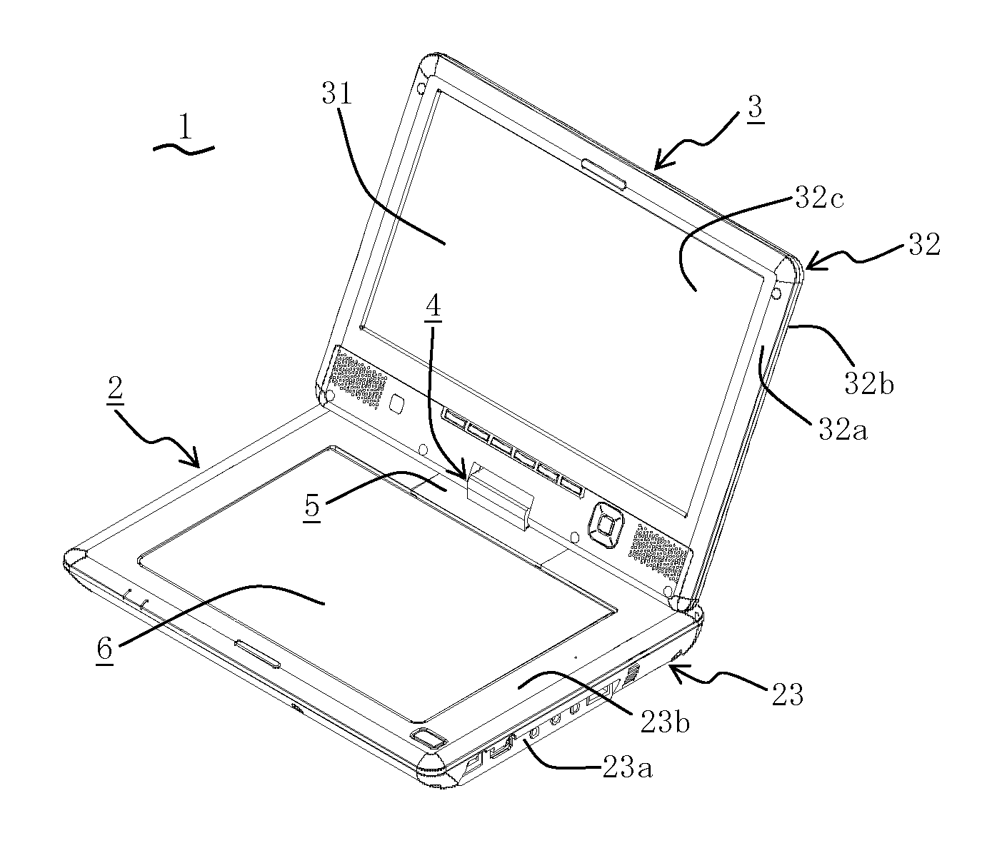
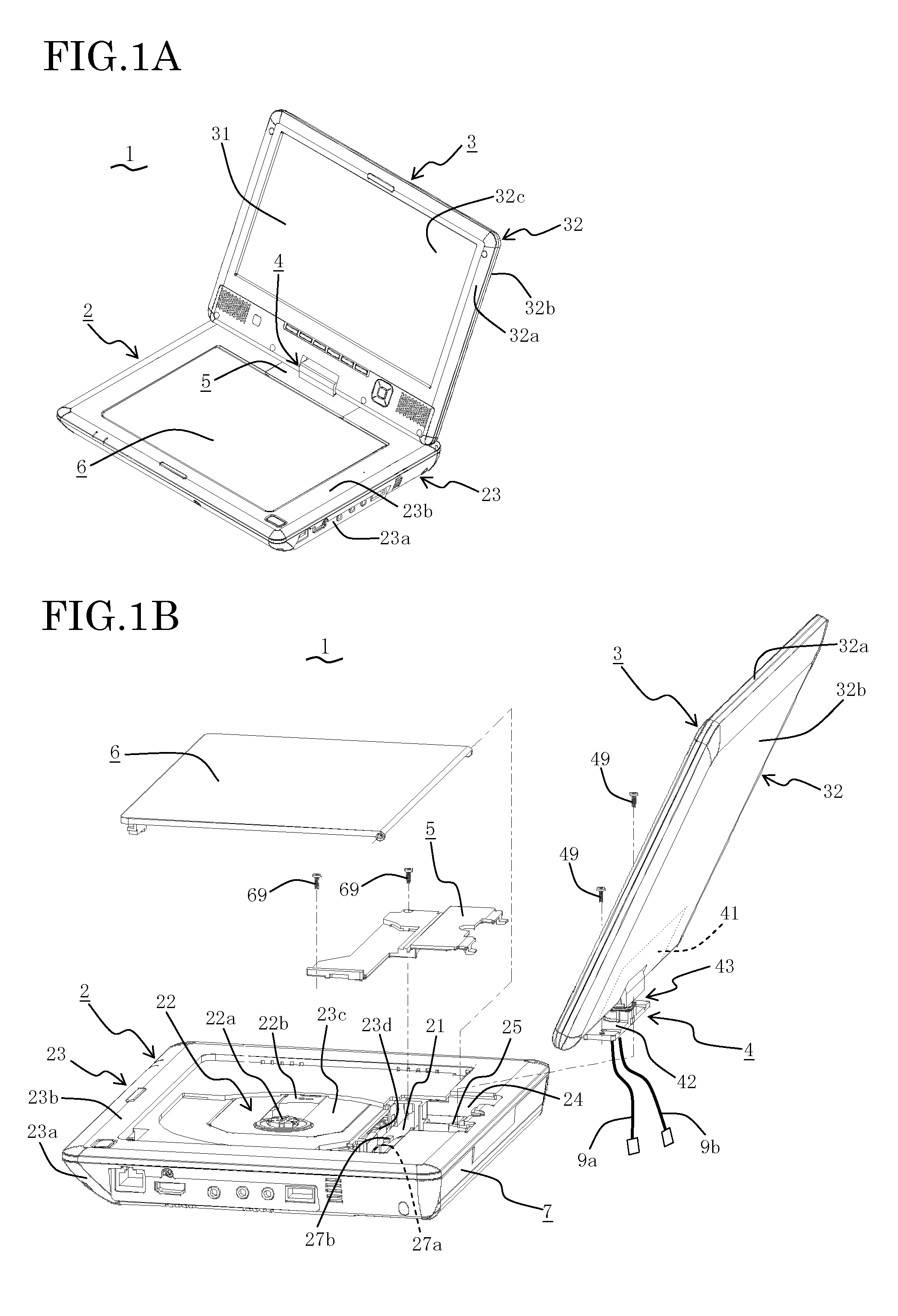
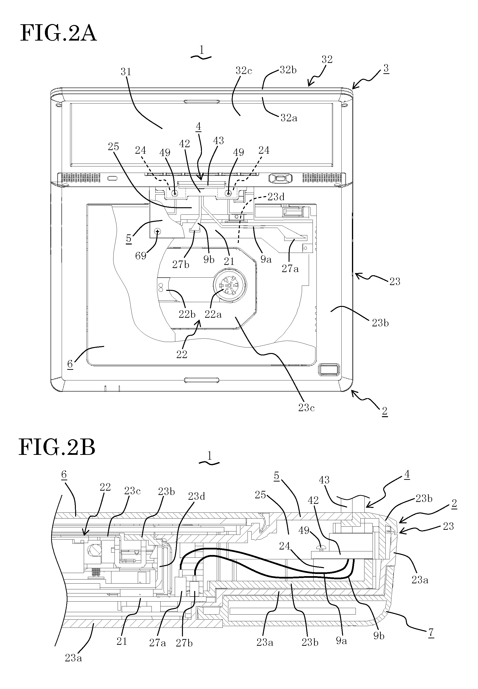
[0019]An optical disc reproduction apparatus 1 as an electronic apparatus according to an embodiment of the present invention will be described with reference to FIGS. 1A, 1B and FIGS. 2A, 2B. FIG. 1A is a schematic perspective view, and FIG. 1B is a schematic exploded perspective view of the optical disc reproduction apparatus 1. FIG. 2A is a schematic plan view of the optical disc reproduction apparatus 1, while FIG. 2B is a schematic cross-sectional view of a part of the optical disc reproduction apparatus 1. The optical disc reproduction appara...


PUM


Abstract

An optical disc reproduction apparatus as an electronic apparatus comprises a display unit mounted on a main body unit via a hinge unit. The main body unit comprises a main body case and a hinge connecting portion provided in a hinge housing portion formed in the main body unit. The hinge housing portion is recessed downward from its periphery in the main body case, and has an opening facing outward from the main body case. A main body-side joint member of the hinge unit is introduced into the hinge housing portion from outside the main body case in a state where upper and lower cases of the main body case are connected to each other (state where the main body unit is already assembled). The main body-side joint member, while housed in the hinge housing portion, is connected to the hinge connecting portion.

Description

BACKGROUND OF THE INVENTION[0001]1. Field of the Invention[0002]The present invention relates to an electronic apparatus having a function to display images.[0003]2. Description of the Related Art[0004]In some of conventional electronic apparatus having a function to display images, a display unit for displaying images is mounted on a main body unit via a hinge unit, in which the display unit can pivot relative to the main body unit (for example, refer to Japanese Laid-open Patent Publications 2003-152357, 2004-162888, 2007-328529 and 2007-300440 as well as Published Japanese Translation of PCT Application 2007-535224). Generally, in such electronic apparatus, the main body unit has a main body case housing a control board, in which the main body case is composed of an upper case and a lower case that are connected to each other. For connecting the hinge unit to the main body unit, the hinge unit is connected to a hinge connecting portion provided on an inner surface of the main bod...

Claims


Application Information

Patent Timeline
IPC IPC(8): H05K7/00G06F1/16
CPCG06F1/162G06F1/1681G06F1/1658
Inventor MIYAGI, JUNJIKUME, HIDEKIMUROI, MARIYAMAMOTO, TAKAYUKI
Owner FUNAI ELECTRIC CO LTD
Why Eureka
Try Eureka