Plug connector having a circuit board with an encryption chip connected to a terminal

a technology of encryption chip and circuit board, applied in the field of plug connectors, can solve the problem that the encryption chip cannot be read, and achieve the effect of simple production process, lower production cost, and higher assembly efficiency

Active Publication Date: 2018-06-05
CHENG UEI PRECISION IND CO LTD
View PDF4 Cites 0 Cited by
  • Summary
  • Abstract
  • Description
  • Claims
  • Application Information

AI Technical Summary

Benefits of technology

[0005]As described above, the second terminal is fastened to the dielectric body, the front end of the second terminal elastically projects beyond the docking surface of the dielectric body, and the rear end of the second terminal projects beyond the rear surface of the dielectric body and is soldered to the circuit board, an encryption chip is read by virtue of the second terminal of the plug connector for satisfying a variety of needs of users, so that the plug connector has the On-The-Go (OTG) function. Furthermore, the plurality of the first terminals and the second terminal are integrally formed, the plurality of the first terminals and the second terminal are integrally molded to the dielectric body. As a result, the plug connector has simple production processes, a higher assembling efficiency and a lower production cost.

Problems solved by technology

However, when the conventional plug connector is connected with an electronic equipment, especially a mobile device, the conventional plug connector is without an On-The-Go (OTG) function, so the conventional plug connector can just realize data transmissions by virtue of connecting with a computer host.
Moreover, an encryption chip is incapable of being read by virtue of the conventional plug connector.

Method used


Image

  • Plug connector having a circuit board with an encryption chip connected to a terminal
  • Plug connector having a circuit board with an encryption chip connected to a terminal
  • Plug connector having a circuit board with an encryption chip connected to a terminal

Examples


Embodiment Construction

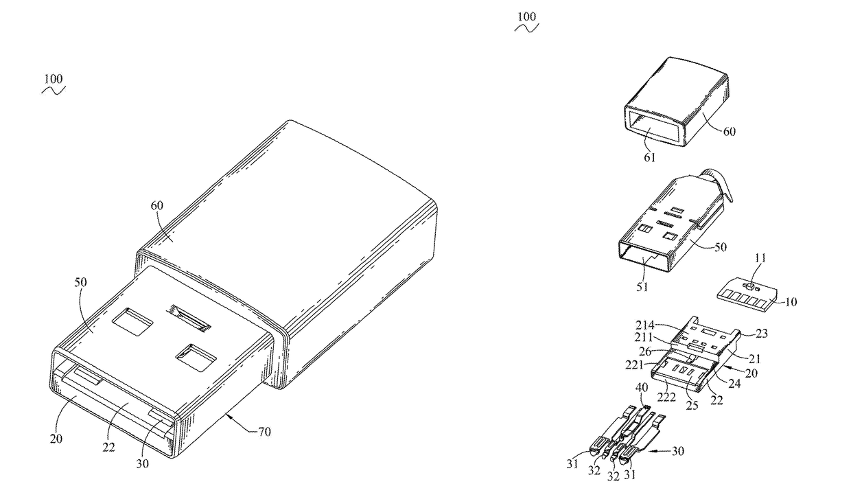
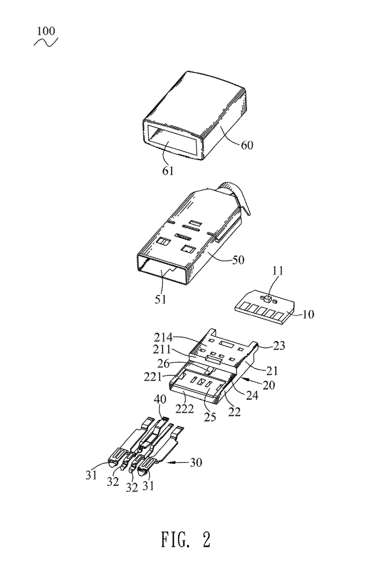
[0014]With reference to FIG. 1 and FIG. 2, a plug connector 100 in accordance with a preferred embodiment of the present invention is shown. The plug connector 100 includes a circuit board 10, a dielectric body 20, a plurality of first terminals 30, a second terminal 40, a shielding shell 50 and an insulating housing 60. The plug connector 100 has an On-The-Go (OTG) function.

[0015]Referring to FIG. 2, FIG. 3 and FIG. 7, the dielectric body 20 has a docking surface 24. Specifically, the dielectric body 20 has a base portion 21. The base portion 21 has a front surface 211, a rear surface 212 opposite to the front surface 211, a bottom surface 213 connected between bottoms of the front surface 211 and the rear surface 212, and a top surface 214 opposite to the bottom surface 213 and connected between tops of the front surface 211 and the rear surface 212. A lower portion of the front surface 211 of the base portion 21 protrudes in a frontward direction to form a tongue board 22. The to...


PUM


Abstract

A plug connector includes a dielectric body having a docking surface, a circuit board mounted to a rear of the dielectric body, a plurality of first terminals and a second terminal. The plurality of the first terminals are fastened to the dielectric body. Top surfaces of front ends of the plurality of the first terminals are exposed to the docking surface of the dielectric body. Rear ends of the plurality of the first terminals project beyond a rear surface of the dielectric body and are soldered to the circuit board. The second terminal is fastened to the dielectric body. A front end of the second terminal elastically projects beyond the docking surface of the dielectric body, and a rear end of the second terminal projects beyond the rear surface of the dielectric body and is soldered to the circuit board.

Description

BACKGROUND OF THE INVENTION1. Field of the Invention[0001]The present invention generally relates to a connector, and more particularly to a plug connector having an On-The-Go function.2. The Related Art[0002]Usually, a conventional plug connector generally includes an insulating housing, two signal terminals and two power terminals. The conventional plug connector is a universal serial bus connector. A lower portion of a front surface of the insulating housing protrudes frontward to form a tongue board. The two signal terminals and the two power terminals are fastened to the insulating housing and arranged transversely. Top surfaces of front ends of the two signal terminals and the two power terminals are exposed to a top surface of the tongue board. However, when the conventional plug connector is connected with an electronic equipment, especially a mobile device, the conventional plug connector is without an On-The-Go (OTG) function, so the conventional plug connector can just re...

Claims


Application Information

Patent Timeline
Patent Type & Authority Patents(United States)
IPC IPC(8): H01R13/66G06F21/72H01R13/6581H01R24/60H01R13/6466H01R107/00
CPCH01R13/6466H01R13/665H01R24/60H01R13/6581G06F21/72H01R2107/00H01R13/6658H01R24/62G06F21/602
Inventor YANG, YU-LINLIU, FENG-TIAN
Owner CHENG UEI PRECISION IND CO LTD
Why Eureka
Try Eureka