Retractable structure for air-conditioning vent

a technology of air conditioner vent and retractable structure, which is applied in ventilation systems, lighting and heating apparatus, heating types, etc., can solve the problems of higher transportation and storage costs, and achieve the effects of ensuring the stability of retracting, low manufacturing accuracy and precision, and saving material

Active Publication Date: 2017-10-03
NINGBO RUNNER INDAL CORP
View PDF6 Cites 0 Cited by
  • Summary
  • Abstract
  • Description
  • Claims
  • Application Information

AI Technical Summary

Benefits of technology

[0007]Therefore, it is a primary objective of the present invention to overcome the problems of the prior art by providing a retractable structure for air-conditioning vent with low manufacturing accuracy and precision, high assembling efficiency and low transportation and storage costs.
[0011]The structure of the present invention requires no additional materials or accessories for the connection of the bracket with the connecting base, and the two latch plates can be cut from the connecting base to save material.
[0013]Compared with the prior art, the retractable structure for air-conditioning vent of the present invention adopts a combination of the connecting plate and the bracket to provide the required elasticity continuously to assure the stability of retracting and stretching the vane in the condition of relatively low manufacturing accuracy and precision, so as to avoid vibrations and noises produced by the vane and deformations occurred in a transportation process. In addition, the retractable mechanism comes with a simplified structure to achieve the effects of reducing the number of components, saving materials, simplifying the manufacturing procedure, and obtaining a high assembling efficiency. In the meantime, the combination of the bracket and the plug hole can provide a more comfortable stretching feeling to users.

Problems solved by technology

In addition, the structure must be packaged separately for transportation and storage, and thus incurring higher transportation and storage costs.

Method used


Image

  • Retractable structure for air-conditioning vent
  • Retractable structure for air-conditioning vent
  • Retractable structure for air-conditioning vent

Examples


Embodiment Construction

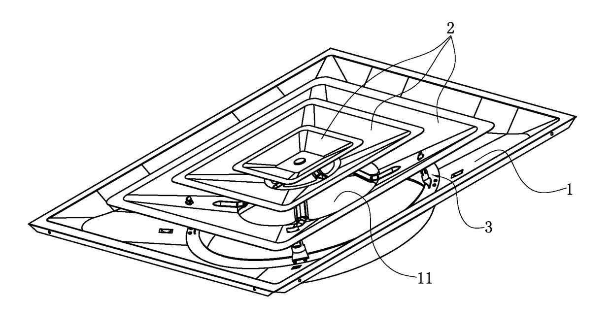
[0024]With reference to FIGS. 1 to 9 of a retractable structure for an air-conditioning vent in accordance with the present invention, the vent includes a main body 1 mounted onto a wall, and the main body 1 has an installing hole 11, and the vane 2 corresponding to the installing hole 11 is installed onto the main body 1 through the retractable mechanism 3.

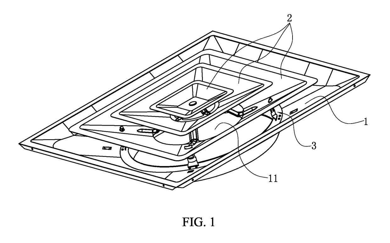
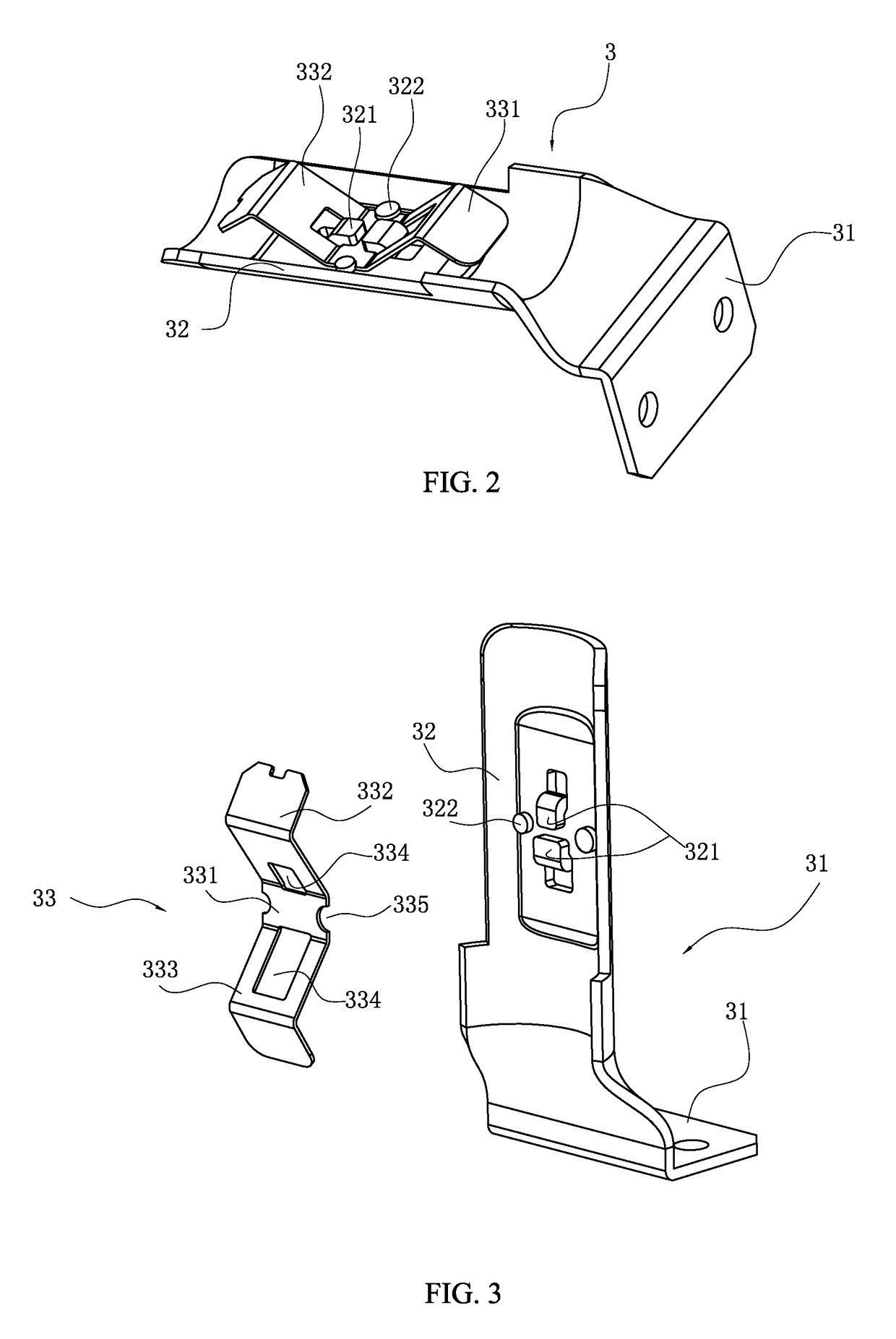
[0025]The retractable mechanism 3 comprises: a bottom plate 31, riveted on the main body 1; a connecting base 32, being perpendicular to the bottom plate 31, and having two latch plates 321 installed at a middle portion of the connecting base 32, and a spread-open surface (not numbered) of the connecting base 32 being in a T-shape, and the middle portion of the connecting base 32 being a flat structure, and the cross-section of the remaining portion of the connecting base 32 is in an arc shape (not shown).

[0026]The bottom plate 31 and the connecting base 32 constitute a connecting plate of this preferred embodiment.

[0027]The brac...


PUM


Abstract

A retractable structure for air-conditioning vent has a retractable mechanism capable of retractably installing a vane into an installing hole of a main body. The retractable mechanism includes a plurality of connecting plates on the main body, and an end of the connecting plates is limited on the main body, and the other end of the connecting plate is passed through a plug hole formed on the vane, and each connecting plate has a bracket on a corresponding side, and a middle portion of the bracket is coupled to the connecting plate, and a first bracket portion and a second bracket portion disposed on both sides of the middle portion of the bracket respectively are outwardly protruded and then inwardly bent to form a stopper portion to stop the plug hole from automatically sliding down.

Description

BACKGROUND OF THE INVENTION[0001]1. Field of Invention[0002]The present invention relates to a retractable structure for an air-conditioning vent.[0003]2. Description of Related Art[0004]As people's standard of living standard improves, central air-conditioning with the features of energy saving, fuel saving, convenient use, and low noise gradually replaces general air-conditioning and it is used extensively in places such as hotel, office and family. The central air-conditioning is mainly composed of four basic components, respectively: a compressor, a condenser, a throttle and an evaporator, and these components are connected sequentially by a pipeline to form a closed system, and a refrigerant is filled into the system and circulated in the system. Through a change of physical state, and a heat exchange with the outside, the temperature of air can be regulated. Wherein, the evaporator is connected to a vent of each room or a local space, so that the cooled or heated air can be de...

Claims


Application Information

Patent Timeline
Patent Type & Authority Patents(United States)
IPC IPC(8): F24F7/00F24F13/06F24F13/08
CPCF24F13/084F24F13/06F24F2221/14
Inventor ZUO, HUA-LIANGSONG, MAO-LIYANG, HONG-TAOHE, YU-JIEXIAO, BIN
Owner NINGBO RUNNER INDAL CORP
Why Eureka
Try Eureka