Smart Servo for a Mechanical CPR System

Inactive Publication Date: 2011-07-07
KONINKLIJKE PHILIPS ELECTRONICS NV
View PDF7 Cites 12 Cited by
  • Summary
  • Abstract
  • Description
  • Claims
  • Application Information

AI Technical Summary

Benefits of technology

[0021]By careful control of the compression depth and shape, thorax and organ damage can be minimize

Problems solved by technology

Firstly, the visco-elastic behavior of the human thorax being very complex and non-linear, an accurate model of the thorax of the specific patient is lacking.
Overshoots (i.e. more deep compressions than desired) can be very dangerous and may cause lethal body damage.
The mechanical system is also subject to overshoots.
If these properties of the mechanical system are not properly taken in consideration, the oscillations and/or

Method used


Image

  • Smart Servo for a Mechanical CPR System
  • Smart Servo for a Mechanical CPR System
  • Smart Servo for a Mechanical CPR System

Examples


Embodiment Construction

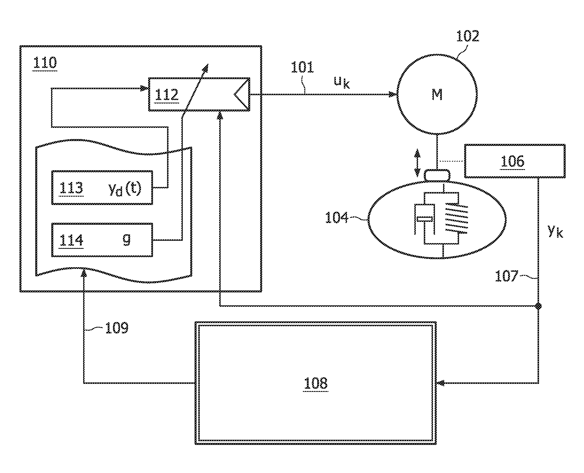
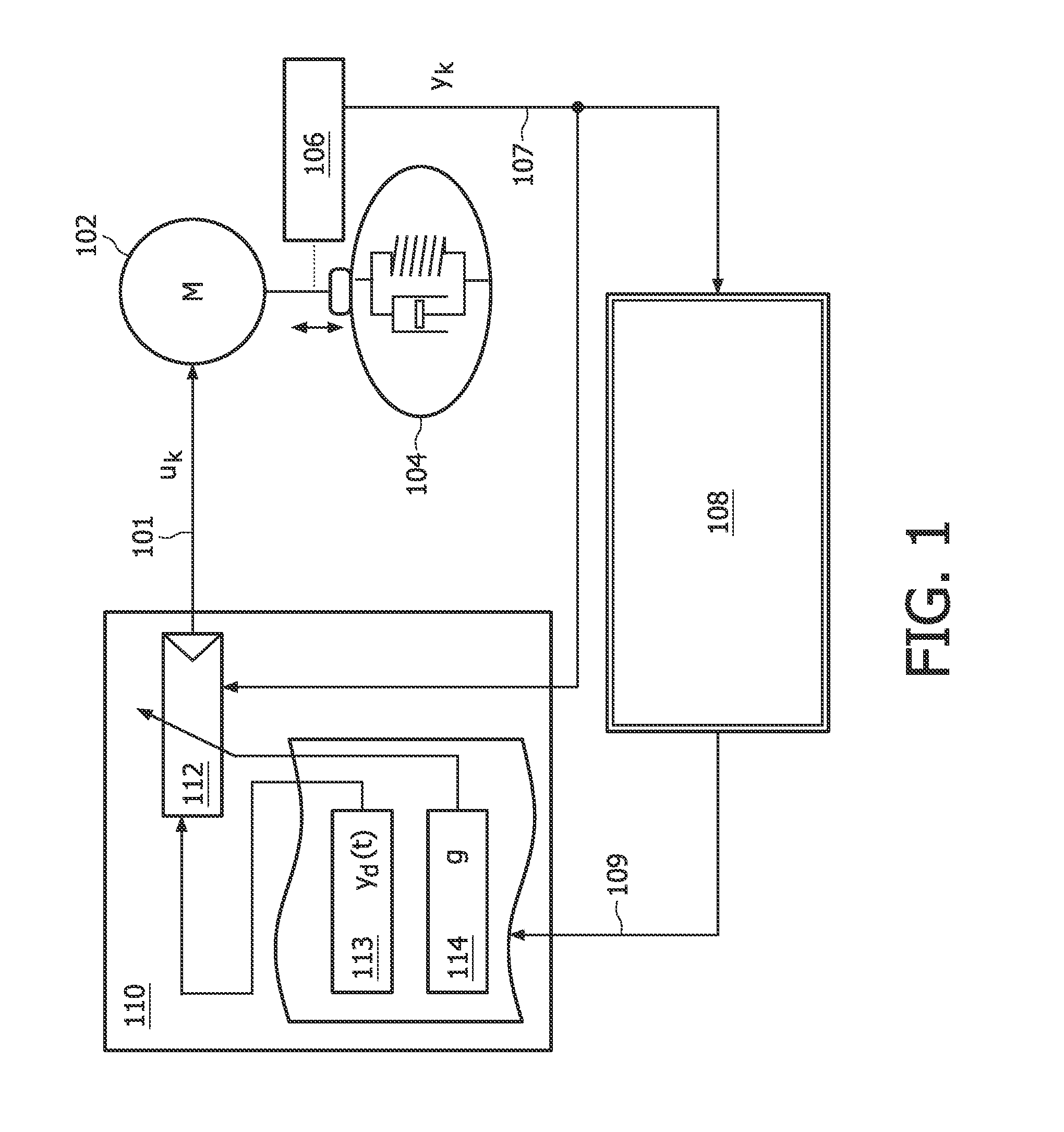
[0047]FIG. 1 shows a schematic block diagram of an automated cardio pulmonary resuscitation apparatus according to a first aspect of the invention. The automated cardio resuscitation apparatus uses a chest compression actuator 102 that exerts a force on a human chest 104 by use of e.g. a pad and a piston. The chest 104 is not a part of the automated cardio pulmonary resuscitation apparatus and is represented by a mechanical model that approximates the mechanical behavior of the chest 104. The mechanical model can be represented by a spring and a damper connected in parallel. The movement of the pad, and consequently also the compression of the chest, is detected by a physiological parameter sensor 106 that provides measurements for the actual chest compression yk. The measurements of the actual chest compression yk are supplied, by means of a connection for the measurements for the actual chest compression 107, to a controller 112 that compares the actual chest compression yk with a...


PUM


Abstract

The invention relates to an apparatus and a method for automated Cardio Pulmonary Resuscitation. The apparatus comprises a chest compression actuator, an actuator driver that supplies time-varying drive signals to the chest compression actuator in dependence of operating parameters of the actuator driver, a physiological parameter sensor supplying measured values of a physiological parameter related to the function of the chest compression actuator, and an adaptive control for the operating parameters of the actuator driver. The operating parameters determining a dynamic behavior of a system comprising the chest compression actuator and a chest of a patient.

Description

FIELD OF THE INVENTION[0001]The invention relates to the field of automated cardiopulmonary resuscitation apparatuses, and more specifically to a control for a chest compression actuator.BACKGROUND OF THE INVENTION[0002]Cardiopulmonary resuscitation (CPR) is a well-known technique for increasing the chance for survival from cardiac arrest. However, it is very difficult to perform consistent high quality manual cardiopulmonary resuscitation. Since CPR quality is key for survival there is a strong drive to have a mechanical automated device to replace less reliable and long duration manual chest compressions. Automated CPR (A-CPR) systems were introduced in the market recently.[0003]Some A-CPR systems use a pneumatic actuator mechanism while other A-CPR systems are driven by an electrical motor such as a servo motor. Patent application publication US 2007 / 0270724 A1 describes a servo motor for CPR that features a control of the compression wave form as applied to the patient. To this ...

Claims


Application Information

Patent Timeline
IPC IPC(8): A61H31/00
CPCA61H2201/018A61H31/004
Inventor WOERLEE, PIERRE H.DE HOOG, THOMAS J.PAULUSSEN, IGOR W. F.AYATI, SHERVIN
Owner KONINKLIJKE PHILIPS ELECTRONICS NV
Why Eureka
Try Eureka