Engine with exhaust gas treatment apparatus

a technology of exhaust gas treatment and treatment apparatus, which is applied in the direction of mechanical apparatus, engine components, machines/engines, etc., can solve the problems of prior art and achieve the effect of reducing the load applied to the exhaust pipe 13 and high rigidity

Active Publication Date: 2011-07-14
KUBOTA LTD
View PDF14 Cites 57 Cited by
  • Summary
  • Abstract
  • Description
  • Claims
  • Application Information

AI Technical Summary

Benefits of technology

[0015]The Invention of claim 1 offers the following effect.
[0016]<<Effect>> The exhaust pipe can be prevented from being damaged by a vibration of the engine body.
[0017]As illustrated in FIGS. 8, 14, 21, and 28, the exhaust gas treatment apparatus 4 is supported by the engine body 1 through the connection flanges 8, 9, 10, and 11. Accordingly, the exhaust gas treatment apparatus 4 is robustly supported by the engine body 1 through the connection flanges 8, 9, 10, and 11 having higher rigidity. Although the exhaust gas treatment apparatus 4 is shaken by a vibration of the engine body 1, load applied to the exhaust pipe 13 can be reduced and the exhaust pipe 13 can be prevented from being damaged by a vibration of the engine body 1.
[0019]The Invention of claim 2 offers the fo...

Problems solved by technology

However, the prior art is problematic in that the exhaust gas treatment ...

Method used


Image

  • Engine with exhaust gas treatment apparatus
  • Engine with exhaust gas treatment apparatus
  • Engine with exhaust gas treatment apparatus

Examples


first embodiment

[0137]The construction of the first embodiment is described below.

[0138]As shown in FIG. 8, in the state in which a direction along which a crank shaft center line 16 extends is forward and backward directions and the width direction of an engine body 1 orthogonal to the crank shaft center line 16 is left and right directions, the engine body 1 has a cylinder head 19 attached above a cylinder block 52, a head cover 20 attached above the cylinder head 19, an oil pan 53 attached under the cylinder block 52, a coolant pump 54 attached in front of the cylinder block 52, an engine cooling fan 18 disposed in front of the coolant pump 54, a gear casing 15 disposed in the rear of the cylinder block 52, a flywheel housing 51 disposed in the rear of the gear casing 15, a suction manifold 56 attached on the right side of the cylinder head 19, and an exhaust manifold 55 attached on the left side of the cylinder head 19 as shown in FIG. 9.

[0139]As shown in FIG. 8, the engine cooling fan 18 is di...

second embodiment

[0214]The construction of the second embodiment shown in FIGS. 14 to 20 is described below.

[0215]As shown in FIG. 15, the EGR apparatus has an EGR cooler 60 and an EGR gas lead-out pipe 135 disposed in an EGR gas lead-out passage 133 and an EGR valve casing 59 disposed on the down stream side of the EGR gas lead-out pipe 135. As shown in FIG. 18, an EGR gas inlet pipe 137 is led out from the suction manifold 56.

[0216]A shown in FIG. 15, an exhaust gas treatment apparatus 4 is coupled to a super charger 62, attached to an exhaust manifold 55, through a flange. The exhaust gas treatment apparatus 4 is a DPF muffler, but it has a larger external size and heavier weight than a conventional muffler. The weight of the exhaust gas treatment apparatus 4 is 20 to 30 Kg which is 4 to 6 times greater than that of the conventional muffler.

[0217]As shown in FIG. 15, the exhaust gas treatment apparatus 4 is disposed above the back part of the engine body 1 covering the bonnet 107 so that the leng...

third embodiment

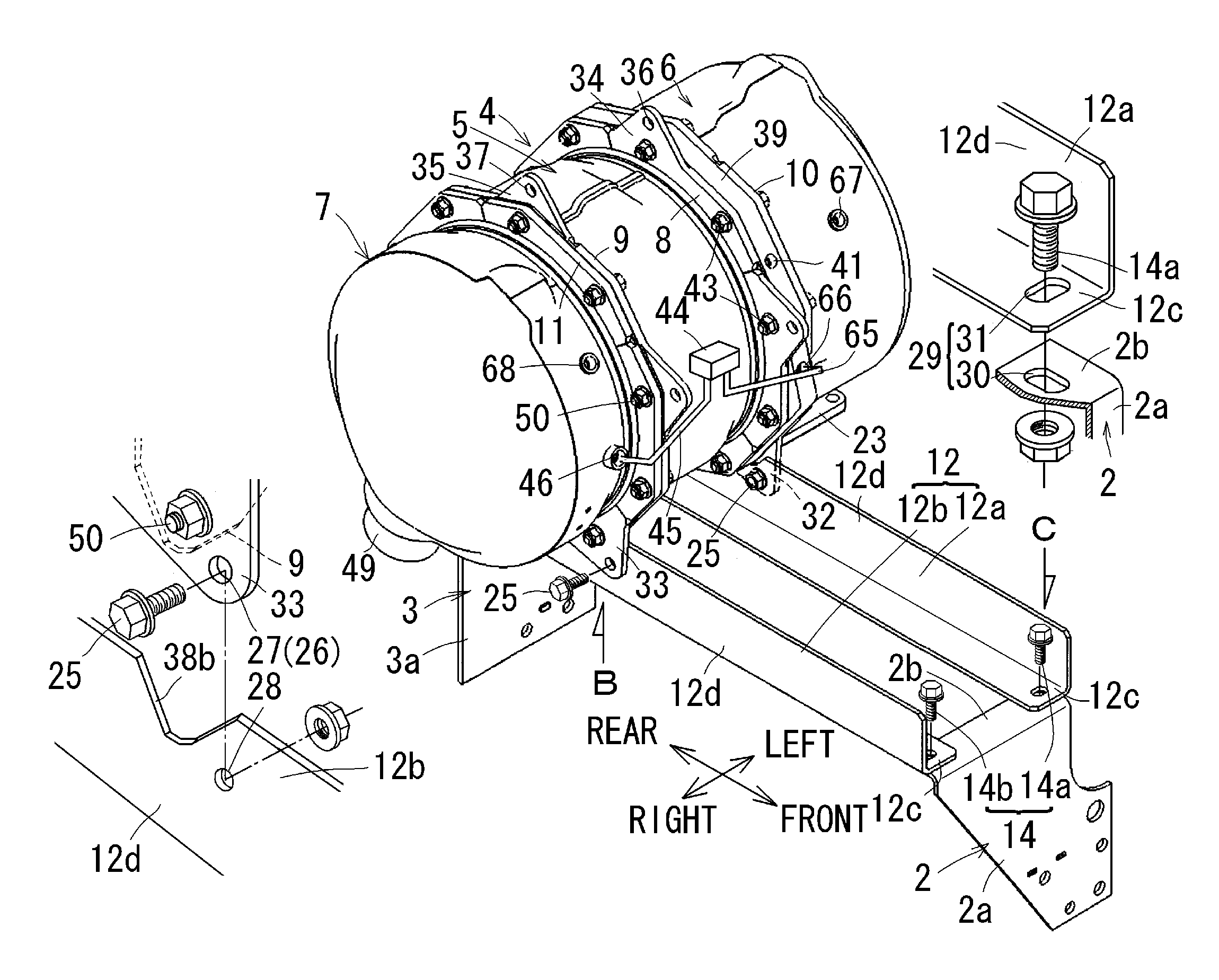
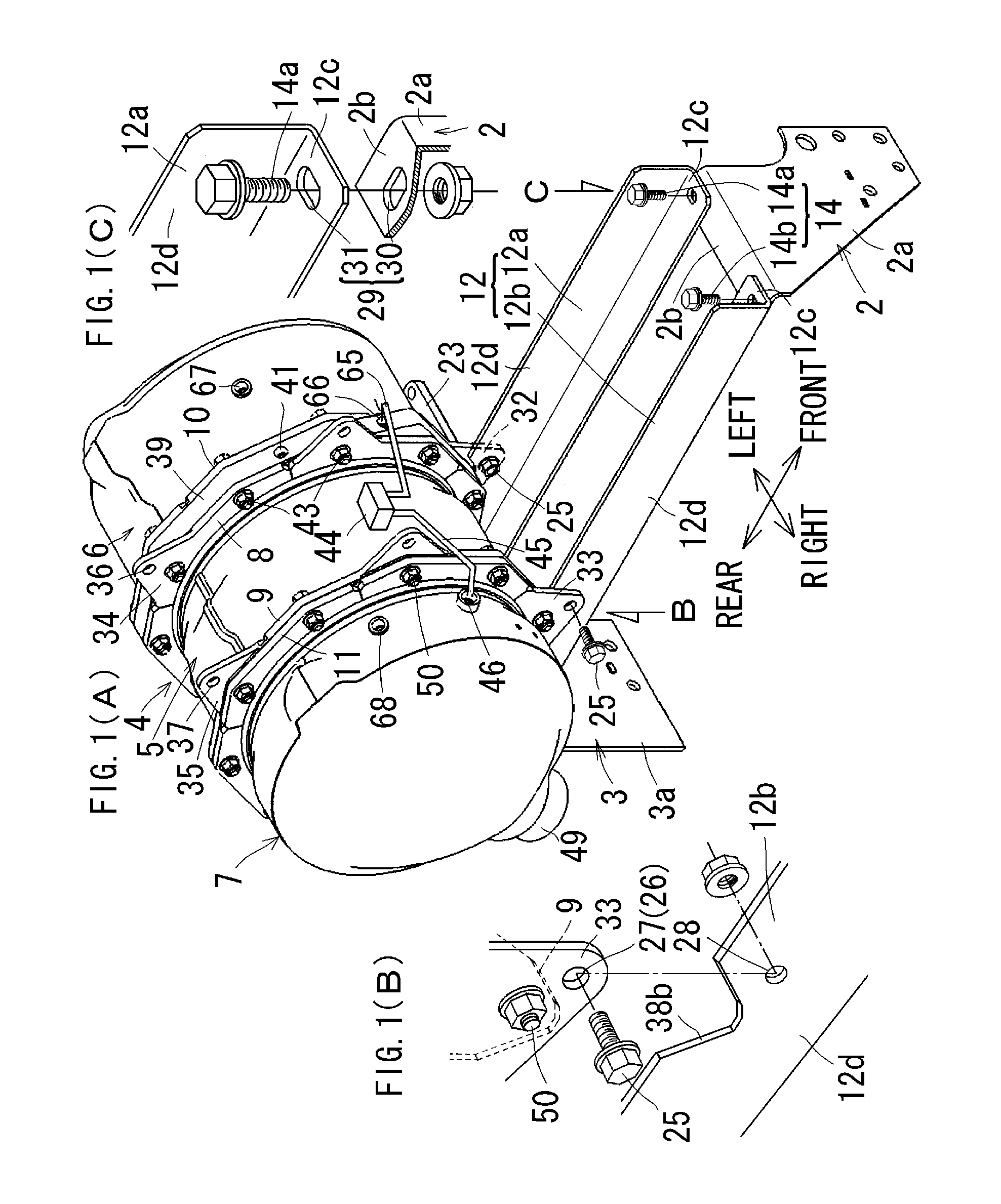
[0235]FIGS. 21 to 27 show a A pair of support brackets 12a and 12b on the left and right sides are disposed in response to respective connection flanges 8 and 9 on the left and right sides of a DPF casing unit 5 placed in a central portion. The front parts of the pair of support brackets 12a and 12b are detachably coupled to the upper portion of a front support stay 2. The back parts of the pair of support brackets 12a and 12b are detachably coupled to the upper portion of the rear support stay 3.

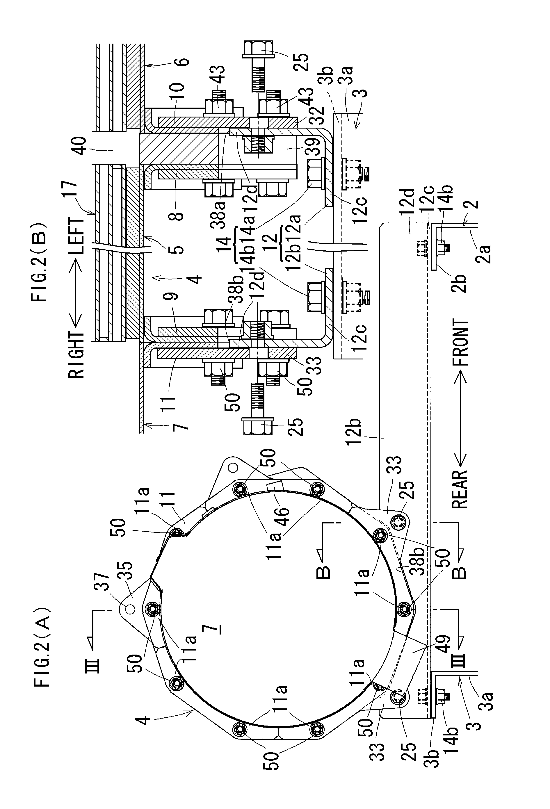
[0236]As shown in FIG. 26, the support unit 12d of the support bracket 12a on the left side is assembled with the lower portion of the connection flange 8 on the left side of the DPF casing unit 5 placed in a central portion and fastened by bracket installation fastening members 25 and 25. The support unit 12d of the support bracket 12b on the right side is assembled with the lower portion of the connection flange 9 on the right side of the DPF casing unit 5 placed in a central portion and...


PUM


Abstract

An object of the present invention is to provide an engine having an exhaust gas treatment apparatus attached thereto, wherein an exhaust pipe 13 can be prevented from being damaged by a vibration of the engine body 1. To achieve the object, in the engine having the exhaust gas treatment apparatus attached thereto in which an exhaust gas treatment apparatus 4 is supported by an engine body 1 and the engine body 1 and the exhaust gas treatment apparatus 4 communicate with each other through an exhaust pipe 13, the casing of the exhaust gas treatment apparatus consists of a plurality of casing units 5, 6, and 7 separable from each other, connection flanges 8, 9, 10, and 11 are disposed in respective end portions of the casing units 5, 6, and 7, the casing units 5, 6, and 7 are coupled together by a connection of the connection flanges 8, 9, 10, and 11, and the exhaust gas treatment apparatus 4 is supported by the engine body 1 through the connection flanges 8, 9, 10, and 11.

Description

TECHNICAL FIELD[0001]The present invention relates to an engine having an exhaust gas treatment apparatus attached thereto and, more particularly, to an engine having an exhaust gas treatment apparatus attached thereto, which is capable of preventing an exhaust pipe from being damaged by a vibration of the main body of the engine.BACKGROUND ART[0002]A conventional engine having an exhaust gas treatment apparatus attached thereto includes an engine in which an exhaust gas treatment apparatus is supported by the main body of the engine and the main body of the engine is configured to communicate with the exhaust gas treatment apparatus through an exhaust pipe (for example, refer to Patent Document 1).[0003]According to this kind of the engine having an exhaust gas treatment apparatus attached thereto, the exhaust gas treatment apparatus is integrated with the main body of the engine. There is an advantage in that the exhaust gas treatment apparatus is easily installed in a machine on ...

Claims


Application Information

Patent Timeline
IPC IPC(8): F01N3/021F01N3/00
CPCF01N13/1822F01N3/08F01N2590/08F01N13/1855F01N13/008F01N13/1805F01N13/1844F01N13/1894F01N3/0335F01N2340/02F01N2450/30F01N2470/18F01N13/0097Y02T10/12F01N13/08F01N13/1838F02B77/00
Inventor KOSAKA, TETSUYASUZUKI, YUSUKEODAWARA, YOSHINOBUOKABE, NOBUYUKI
Owner KUBOTA LTD
Why Eureka
Try Eureka