Burner with split combustion and exhaust induction air paths

Inactive Publication Date: 2011-07-14
ECLIPSE
View PDF13 Cites 10 Cited by
  • Summary
  • Abstract
  • Description
  • Claims
  • Application Information

AI Technical Summary

Benefits of technology

[0004]The present invention provides advantages and alternatives over the prior art by incorporating a system in which the inlet air which is delivered by a blower or other pressure source is split such that a first portion is delivered to a combustion chamber while a second portion is delivered through an annular constriction and into an exhaust outlet in fluid communication with the combustion product gas return path. The

Problems solved by technology

While such prior systems work well, the need for an air supply fe

Method used


Image

  • Burner with split combustion and exhaust induction air paths
  • Burner with split combustion and exhaust induction air paths
  • Burner with split combustion and exhaust induction air paths

Examples


Example

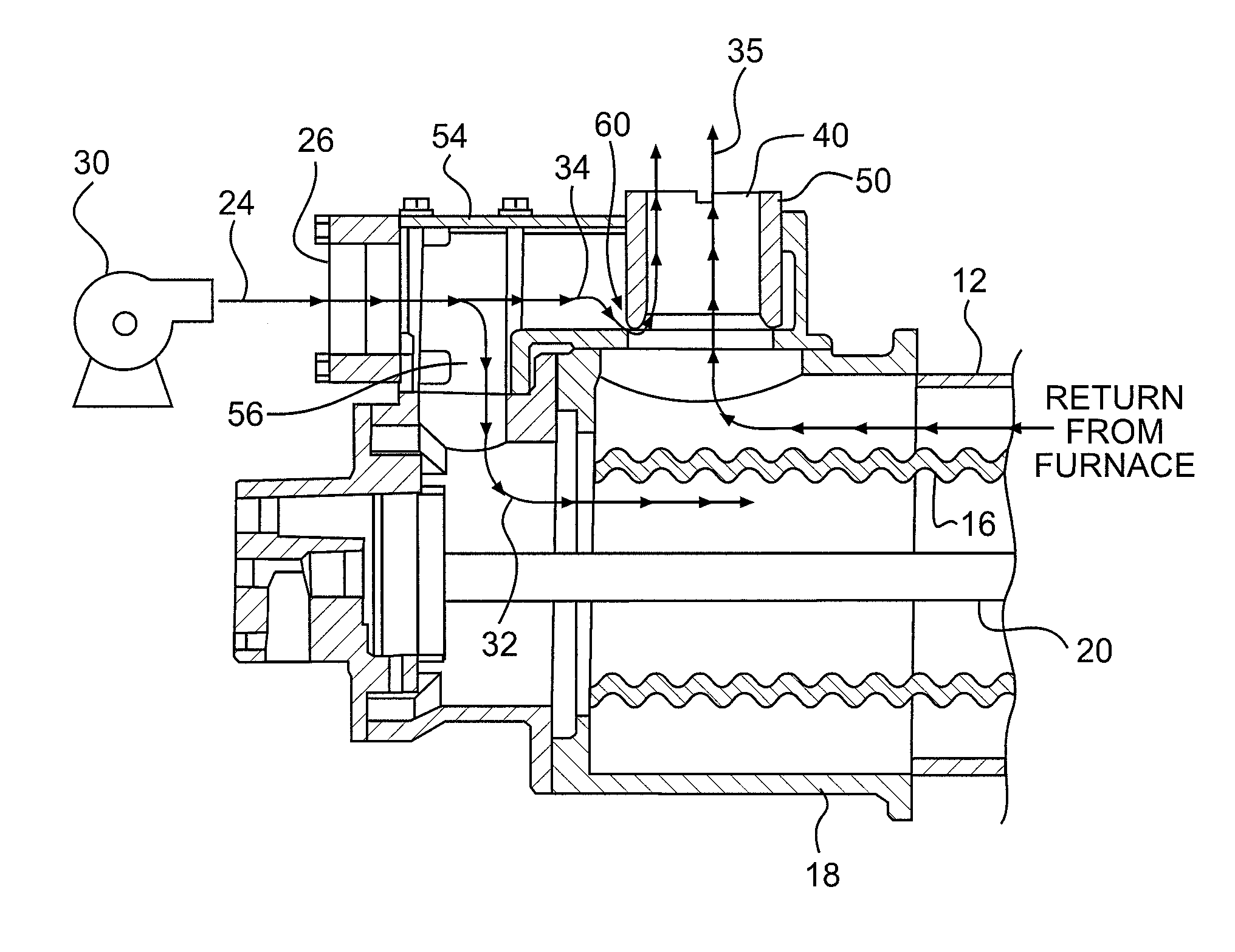
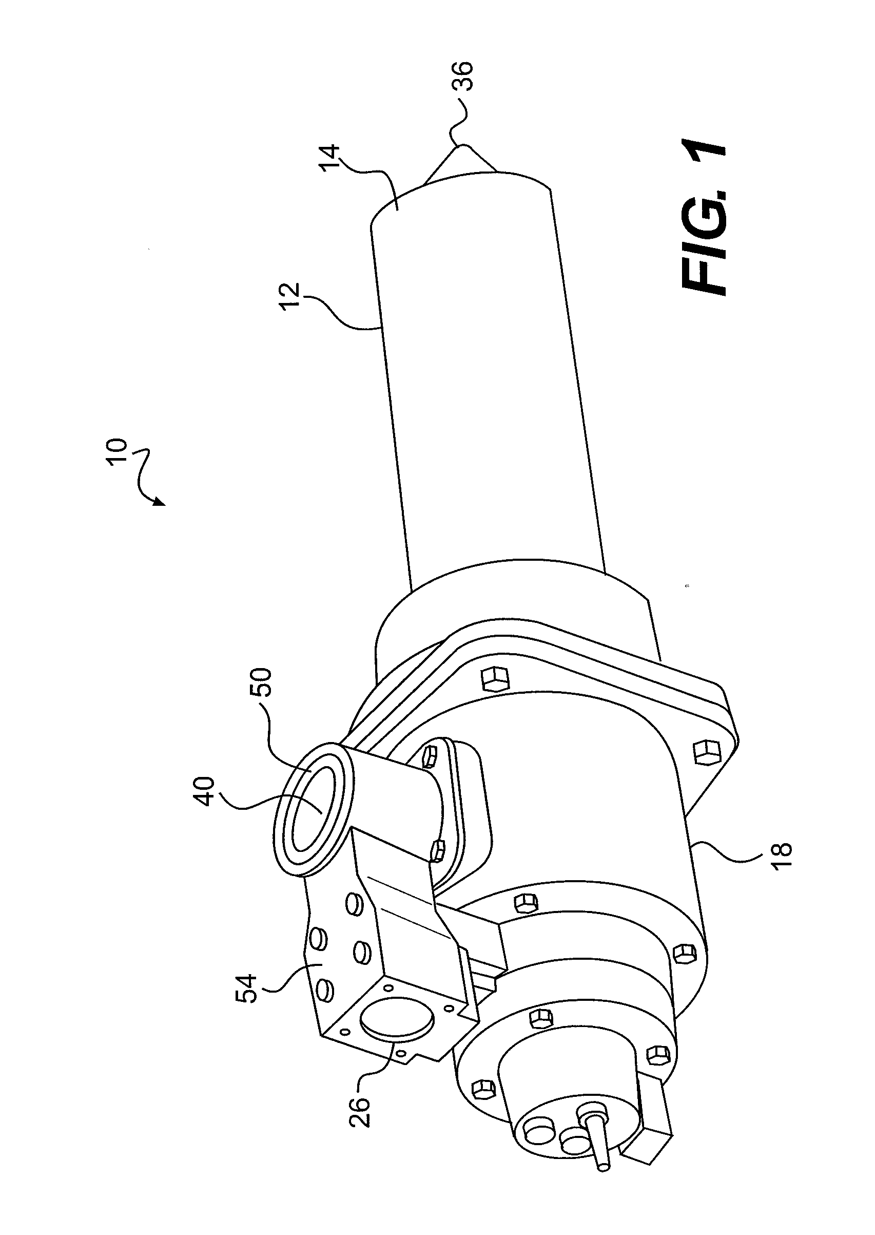
[0021]Reference will now be made to the drawings wherein like elements are designated by like reference numbers in the various views. FIG. 1 illustrates a burner 10 including a generally hollow tubular cover tube 12 having an open end 14 that projects into a furnace or other environment to be heated. As best seen in FIG. 3, the cover tube 12 is disposed in surrounding relation to a hollow, substantially cylindrical heat recuperator 16 of ceramic or the like having a convoluted surface extending outwardly from a housing 18. The recuperator 16 surrounds a fuel tube 20 feeding a burner head within a combustion chamber located adjacent to the open end 14.

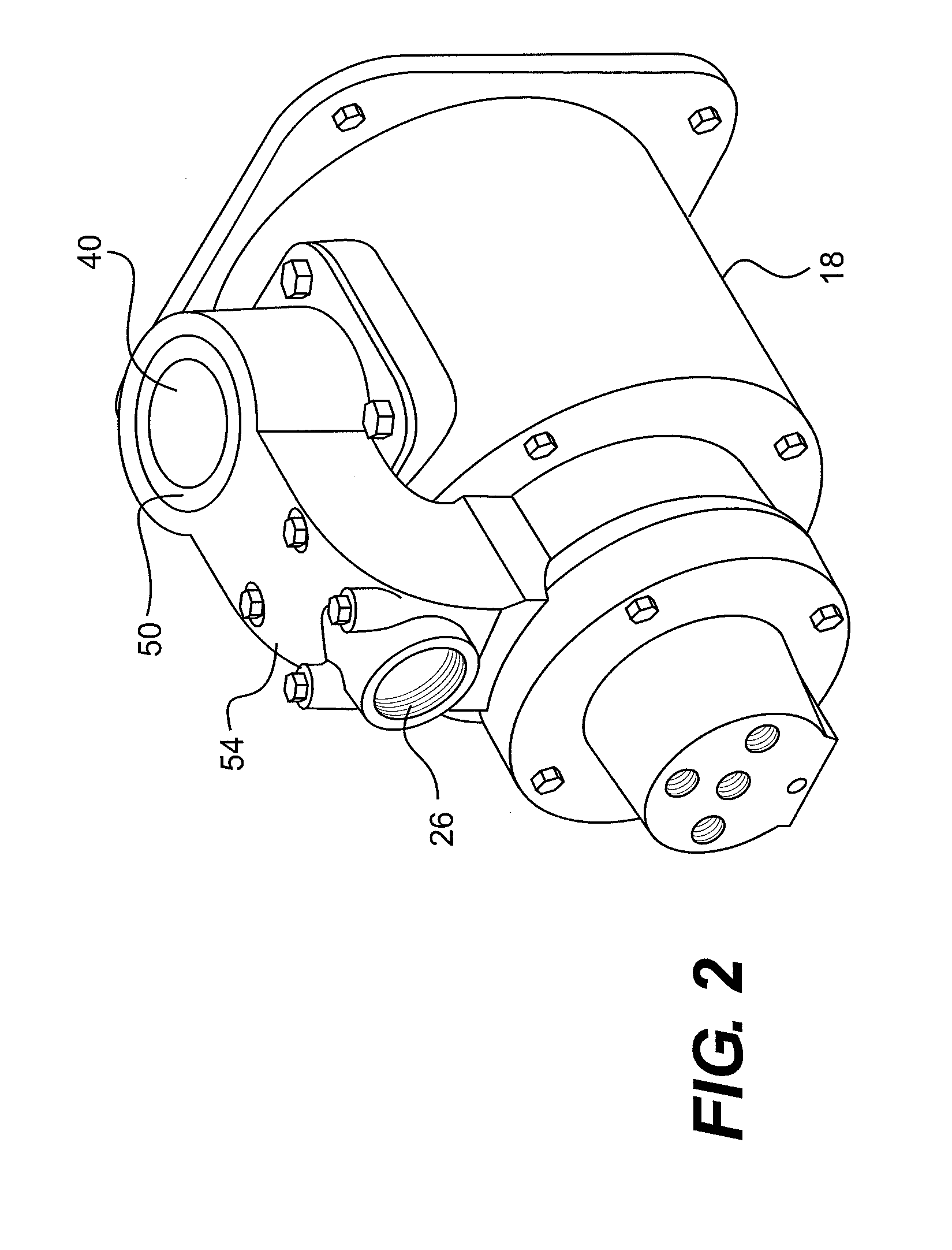
[0022]As shown in FIG. 3, an air supply designated generally as 24 is introduced into an air inlet port 26 from a blower 30 or other suitable supply source. Within the housing 18, the air supply 24 is split into a combustion feed stream 32 and an exhaust induction stream 34. An eductor body 54 is attached to the housing 18. The air inle...


PUM


Abstract

A burner having a fuel tube, a heat recuperator disposed at least partially around the fuel tube, a cover disposed at least partially around the heat recuperator, and a housing coupled to the fuel tube. The housing has an air inlet, an exhaust outlet, and an eductor body. The eductor body has a first pathway for directing inlet air toward the heat recuperator and a second pathway directing inlet air into the exhaust outlet.

Description

CROSS-REFERENCE TO RELATED APPLICATIONS[0001]This patent application claims the benefit of U.S. Provisional Patent Application No. 61 / 294,173, filed Jan. 12, 2010, which is incorporated by reference in its entirety herein.BACKGROUND[0002]Burners that withdraw combustion product gases from a furnace environment are known. Such burners typically incorporate an elongated hollow recuperator of ceramic material or the like that is disposed in spaced-apart surrounding relation to an axial gaseous fuel supply tube leading to a burner head. Dedicated combustion air travels along the annulus between the fuel supply tube and the recuperator for combustion with the gaseous fuel at the burner head. A portion of the combustion product gases then travels back over the exterior of the recuperator in counter-current flow to the combustion air. When the burner has an open- ended construction, the combustion product gases are typically drawn out of the furnace and into a low pressure venturi exhaust ...

Claims


Application Information

Patent Timeline
IPC IPC(8): F23L17/16F23D14/66F23J11/00
CPCF23D14/66F23C7/008Y02E20/34
Inventor COLLIER, DAVID
Owner ECLIPSE
Why Eureka
Try Eureka