
Device and method for controlling a prestressing jack when tensioning a tendon

a technology of prestressing jack and tensioning ring, which is applied in the direction of girders, wire tools, manufacturing tools, etc., can solve the problems of essentially limited manual labor, and achieve the effect of preventing the tensioning process of the prestressing ring, reducing labor and expense, and facilitating the tensioning of the ring members

Active Publication Date: 2011-07-14
DYWIDAG SYST INT GMBH (DE)
View PDF10 Cites 15 Cited by
  • Summary
  • Abstract
  • Description
  • Claims
  • Application Information

AI Technical Summary

Benefits of technology

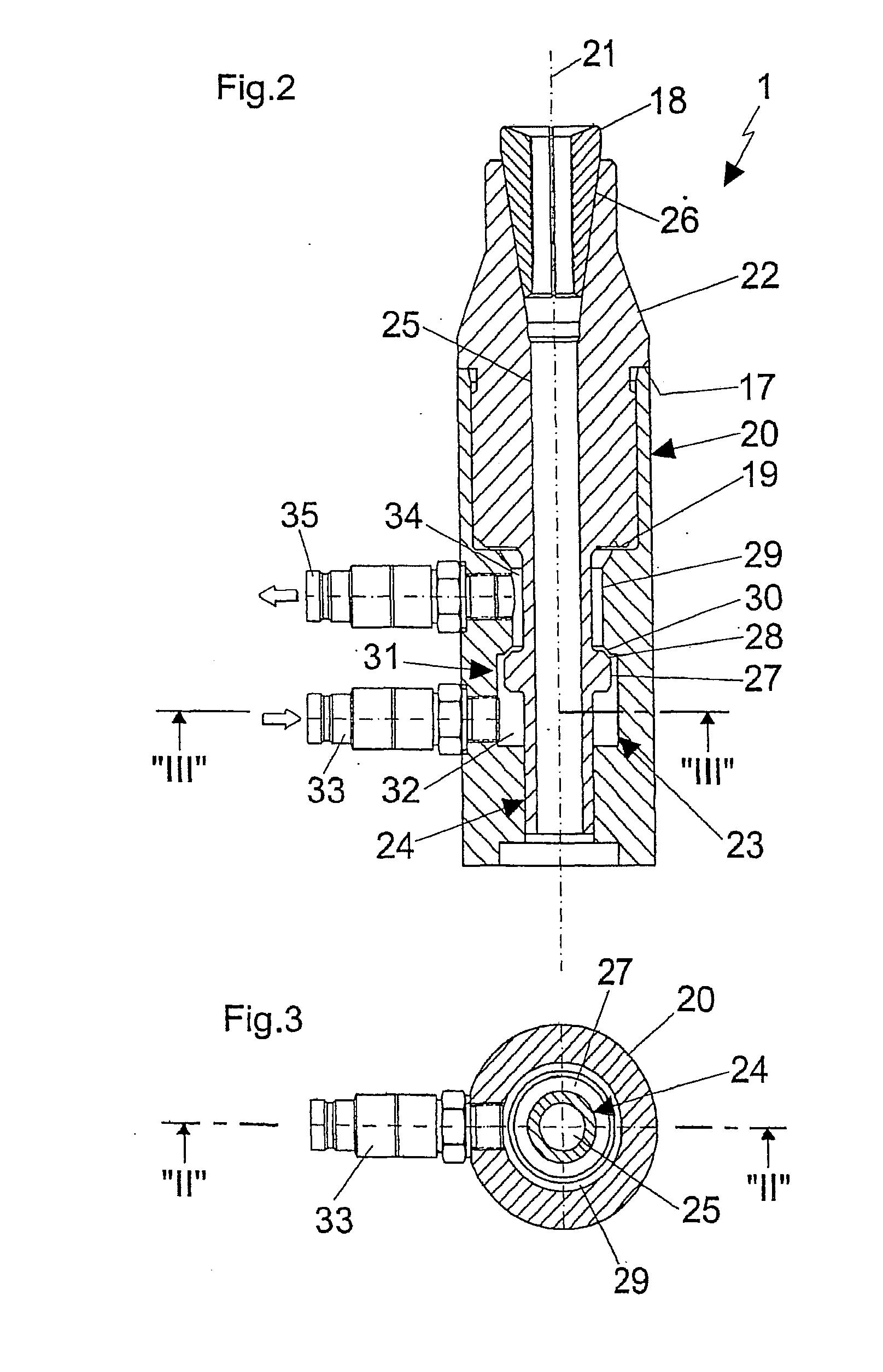
[0012]A first advantage of the invention results from the maximally automatic progress of the tensioning process. Once the reference tension member and the prestressing jack have been set up, there is no need for complex control devices or further actions on the part of the operating personnel, such as taking measurements or switching off the prestressing jack at the right time. The manual labor is essentially limited to switching the prestressing jack from one tension member to the next. Consequently, the invention makes it possible for tension members to be tensioned easily and quickly and also precisely and reliably, with minimal labor and expense.
[0013]In an embodiment, a valve unit is provided that is actuated as a function of the stroke motion of a piston and that controls the supply of pressure medium for the prestressing jack. In this regard, the invention encompasses all types of valves, of which that shown in the figures represents only one embodiment. This embodiment provides for arranging the valve unit in the pressure space—that is enclosed by the housing and piston—through which the pressure medium flows on the way to the prestressing jack. The piston motion interrupts this flow path with the aid of the valve, and thus stops the prestressing jack's tensioning process.
[0014]In an embodiment of the invention, the valve unit has a valve tappet that is directly connected to the piston, an effect which can also be achieved by a one-piece design of the piston and tappet. This results in a device that is extremely simple and compact and operates extremely precisely as a result of the transmission of force from the piston to the tappet without play. The precision, and hence the reliability, of the valve unit are further increased by the mounting of the valve tappet in an axial plain bearing at the end opposite the piston.
[0015]Additional advantages are achieved by the means that the reference tension member is anchored directly to the piston of the inventive device and additionally passes through it along its longitudinal axis. Overall, this results in an extremely compact construction, which is of great utility in view of the cramped conditions in the anchorage zone of the tension members.
[0016]In order to improve the functionality of an inventive device, said device can be expanded by means of a tensioning module that is interposed between the wedge plate and the piston, and with which the already prestressed reference tension member is additionally tensioned by a short distance in order to activate the wedge grip in the region of the anchorage of the reference tension member to the piston. This embodiment of the invention thus offers a maximum of efficiency and operating convenience.

Problems solved by technology

The manual labor is essentially limited to switching the prestressing jack from one tension member to the next.

Method used


Image

  • Device and method for controlling a prestressing jack when tensioning a tendon
  • Device and method for controlling a prestressing jack when tensioning a tendon
  • Device and method for controlling a prestressing jack when tensioning a tendon

Examples


Embodiment Construction

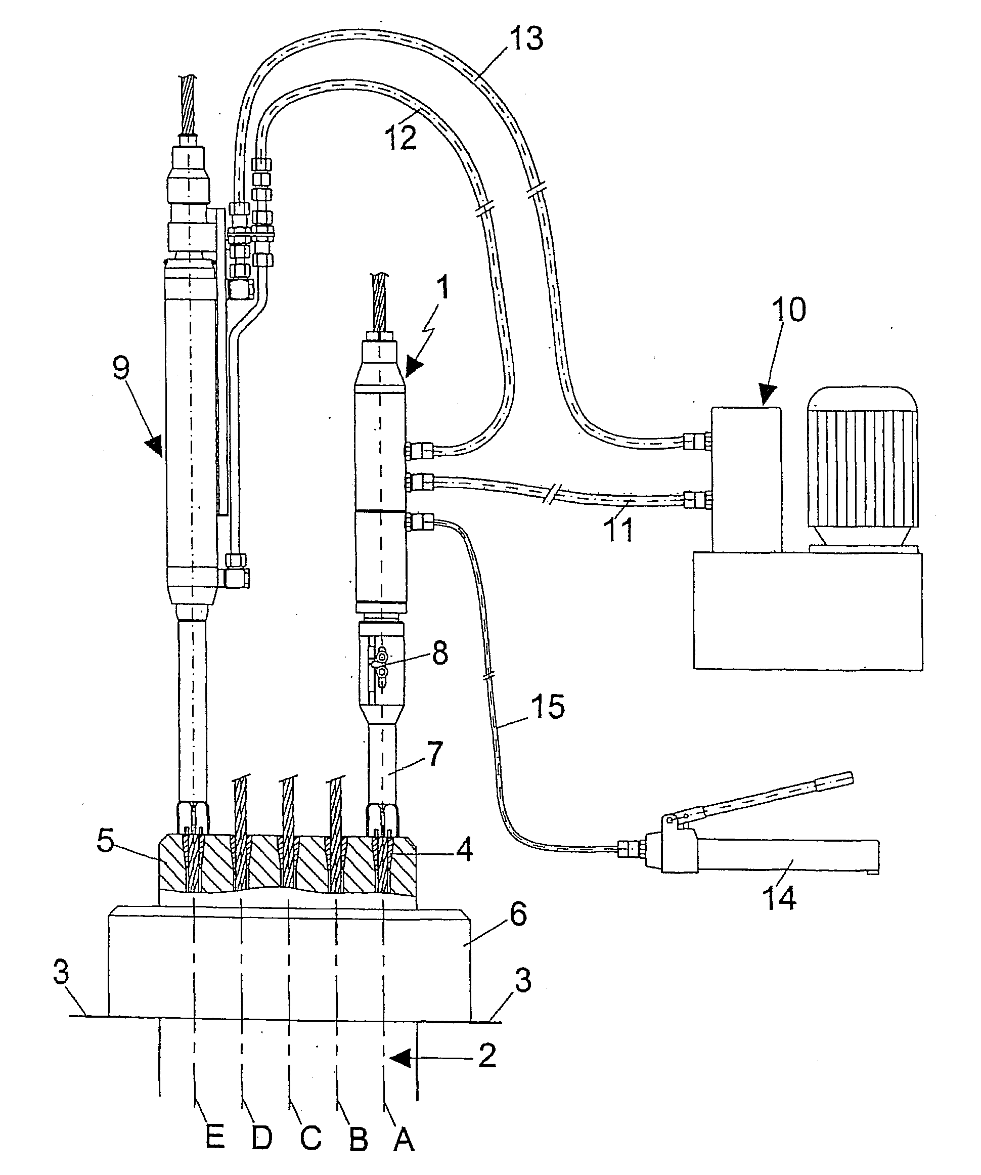
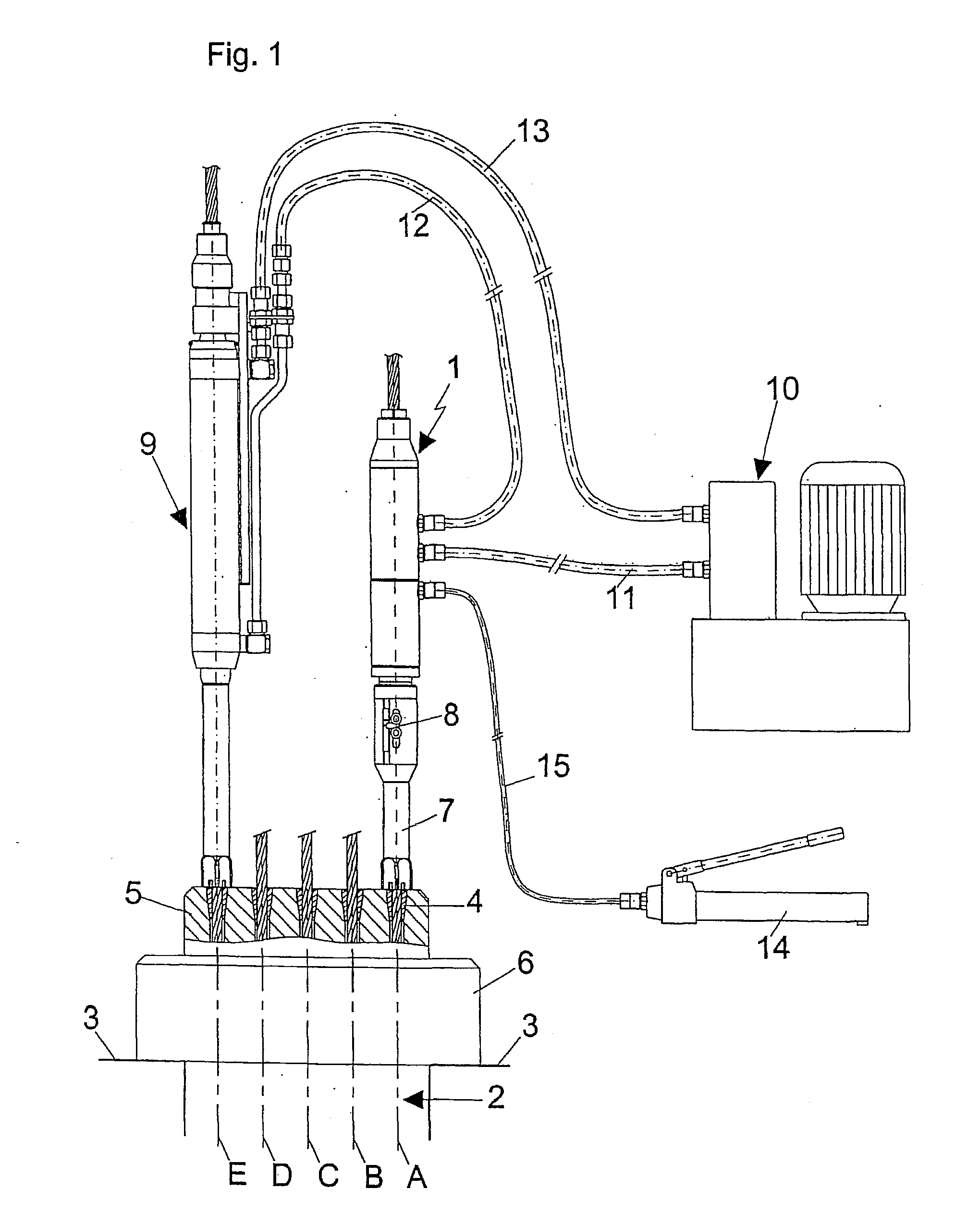
[0023]FIG. 1 gives an overview of a device 1 according to the invention as well as its use in tensioning a multi-strand tendon 2. It can be seen that a prestressed structural member 3 in the anchorage zone of the multi-strand tendon 2 is merely indicated. The multi-strand tendon 2 is composed of a plurality of tension members, of which the tension members A, B, C, D, E are shown as representative for all tension members. The tension members A, B, C, D, E, here in the form of stranded wires, are secured in a known manner with the aid of anchoring wedges 4 in a wedge plate 5, which in turn is seated on an abutment ring 6 that bears against the structural member 3. In the present example, the strand A constitutes the reference tension member, whose tension is used as a reference for tensioning the remaining tension members B, C, D, E. The goal is to produce a uniform state of tension in all the individual tension members A, B, C, D, E for the operational state when tensioning the multi...


PUM

PropertyMeasurementUnit
Forceaaaaaaaaaa
Pressureaaaaaaaaaa
Angleaaaaaaaaaa

Abstract

A device and a method for controlling a clamping press is provided when clamping a tension member as a function of the clamping force of a reference clamping member. The device has a hollow, cylindrical housing, wherein a piston coupled to the reference tension member is supported longitudinally displaceably along an axis. The housing and the piston encompass a pressure chamber that can be acted upon by a pressure medium for performing an axial stroke motion of the piston against the clamping force of the reference tension member by an inlet, and that can be connected by an outlet to the clamping press. The device further comprises a valve unit for controlling the application of the pressure medium to the clamping press, wherein the valve unit can be directly controlled by the stroke motion of the piston. The method according to the invention provides for clamping the tension member as a function of the clamping force of the reference tension member by the cylinder piston unit, the piston thereof holding the reference tension member in a predetermined stress state. When a uniform stress state is achieved in all tension members in the course of clamping the tension member by a clamping press, the inflow of the pressure medium to the clamping press is directly interrupted by the stroke motion of the piston.

Description

[0001]This nonprovisional application is a continuation of International Application No. PCT / EP2009 / 004780, which was filed on Jul. 2, 2009, and which claims priority to German Patent Application No. DE 10 2008 032 881.2, which was filed in Germany on Jul. 14, 2008, and which are both herein incorporated by reference.BACKGROUND OF THE INVENTION[0002]1. Field of the Invention[0003]The present invention relates to a device and method for controlling a prestressing jack when tensioning a tendon.[0004]2. Description of the Background Art[0005]Devices in accordance with the invention are useful in all applications where at least two, but generally many, tension members of a structure are to be tensioned one after the other such that a uniform state of tension prevails in all tension members after the completion of the tensioning process. Cited by way of example are prestressed structures or structural members that, under the compressive preloading introduced during tensioning of the tend...

Claims


Application Information

Patent Timeline
IPC IPC(8): B25B25/00B21F9/00
CPCE04G21/12E04G2021/128E04C5/08E04G21/121E04C3/26E04C5/122
Inventor STEIDINGER, PETERNUETZEL, OSWALDKEINER, HAGEN
Owner DYWIDAG SYST INT GMBH (DE)
Learn More