
3D image processing device and method for reducing noise in 3D image processing device

Inactive Publication Date: 2011-07-14
PANASONIC CORP
View PDF17 Cites 14 Cited by
  • Summary
  • Abstract
  • Description
  • Claims
  • Application Information

AI Technical Summary

Benefits of technology

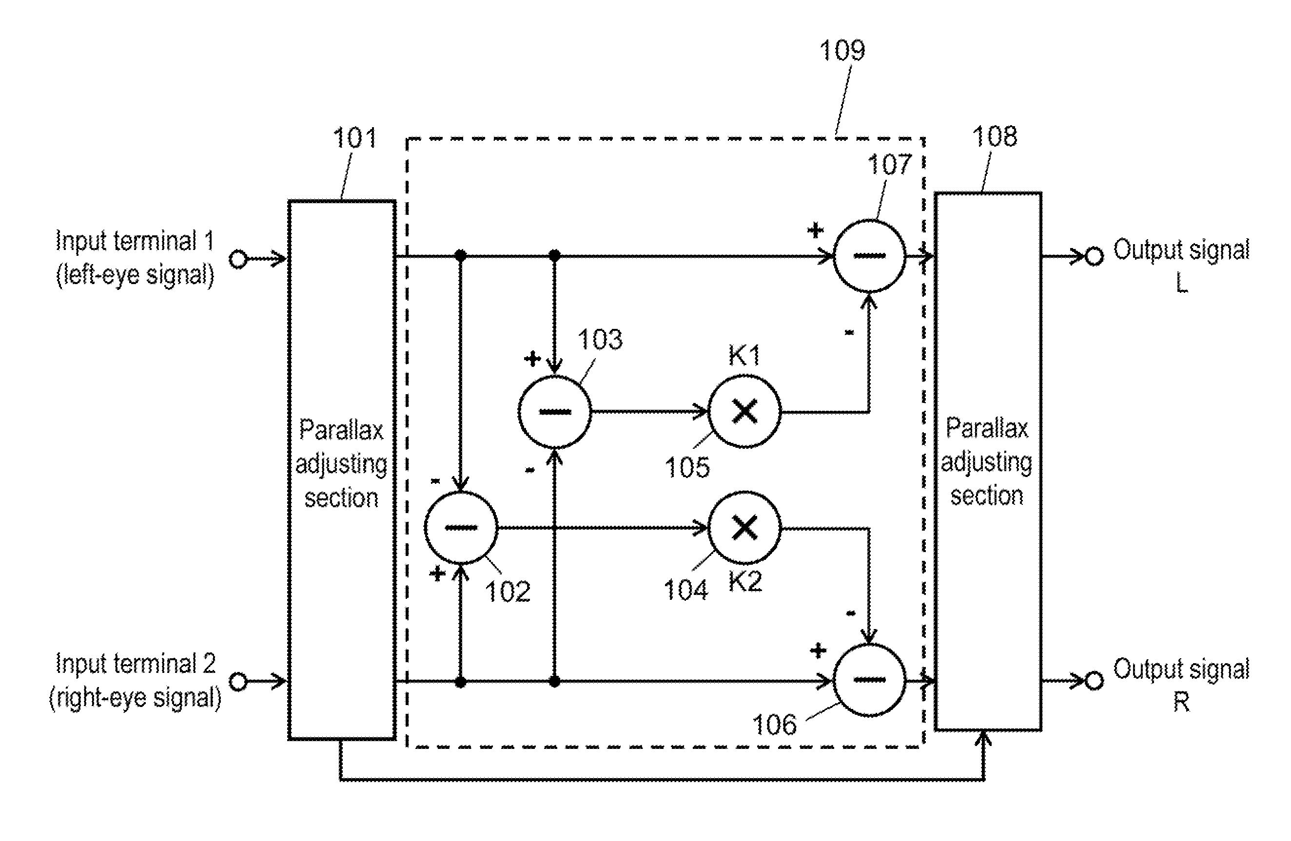
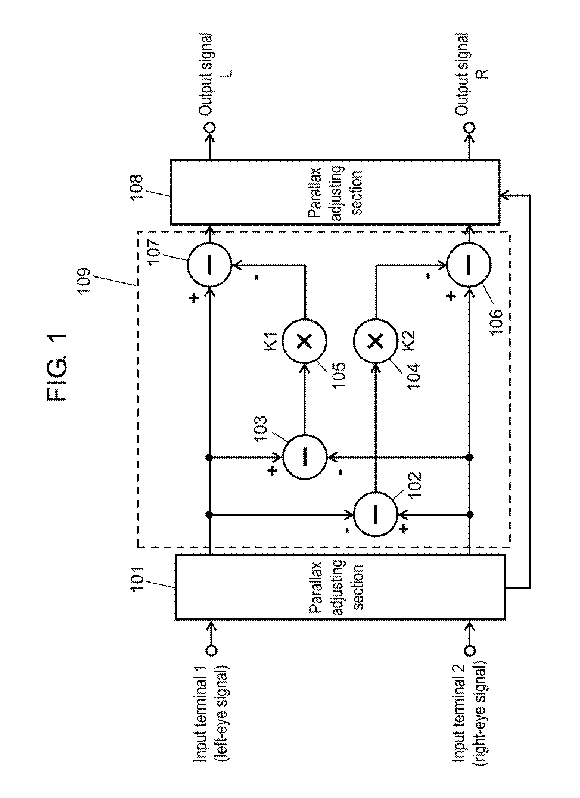
[0013]a second parallax adjusting section for receiving the parallax adjusting information output from the first parallax adjusting section, adjusting the parallax between the parallax adjusted left-eye signal and the parallax adjusted right-eye signal in which noise is reduced by the noise reducing section, and shifting the video position.The noise reducing section calculates a noise level based on the signal level difference between the parallax adjusted left-eye signal and the parallax adjusted right-eye signal between which parallax is eliminated by the first parallax adjusting section, and subtracts the noise level from the signal level of each of the left-eye signal and right-eye signal to reduce the noise in the 3D video signal.
[0014]Thanks to such a configuration, noise in the 3D video where two signal lines for the right eye and left eye are transmitted in parallel can be removed without using frame memory. The right-eye video signal and left-eye video signal are input with the same timing in the time axis direction, so that these signals are hardly affected by a scene change or the like. Thus, noise can be effectively reduced.
[0019]a second parallax adjusting step of receiving the parallax adjusting information acquired in the first parallax adjusting step, adjusting the parallax between the parallax adjusted left-eye signal and the parallax adjusted right-eye signal in which noise is reduced in the noise reducing step, and shifting the video position.In the noise reducing step, a noise level is calculated based on the signal level difference between the parallax adjusted left-eye signal and the parallax adjusted right-eye signal that are acquired in the first parallax adjusting step and have no parallax, and the noise level is subtracted from the signal level of each of the left-eye signal and right-eye signal to reduce the noise in the 3D video signal.

Problems solved by technology

In order to process a 3D video signal where two signal lines for the right eye and left eye are transmitted in parallel, however, this cyclic noise reducing device requires a noise reducing device for the right eye and a noise reducing device for the left eye.
This type of devices cannot always achieve accurate noise reduction in the 3D video signal.
Further, the devices cannot always achieve accurate noise reduction also in a video signal that largely changes before and after the frame due to a scene change or the like because the frame difference becomes large.
When the frame difference increases in the scene change or the like, accurate noise reduction cannot be achieved disadvantageously.

Method used


Image

  • 3D image processing device and method for reducing noise in 3D image processing device
  • 3D image processing device and method for reducing noise in 3D image processing device
  • 3D image processing device and method for reducing noise in 3D image processing device

Examples


Embodiment Construction

[0030]An exemplary embodiment of the present invention is described with reference to the accompanying drawings.

Exemplary Embodiment

[0031]FIG. 1 is one example of a block diagram of a part related to noise reduction of a 3D image processing device in accordance with an exemplary embodiment of the present invention. This device assumes that 3D video is input as two signal lines for the left eye and right eye. The 3D image processing device of the present exemplary embodiment includes the following elements:[0032]parallax adjusting section 101 as a first parallax adjusting section for receiving two video signals of the left-eye signal and right-eye signal from input terminal 1 as the first input terminal and input terminal 2 as the second input terminal, respectively, and adjusting the parallax between the left-eye signal and the right-eye signal;[0033]noise reducing section 109 for receiving a parallax adjusted left-eye signal and a parallax adjusted right-eye signal that are output ...


PUM


Abstract

Multiplication coefficients K1 and K2 in a first multiplying section and a second multiplying section are controlled based on the correlation in a parallax adjusted right-eye signal and a parallax adjusted left-eye signal output from a first parallax adjusting section respectively or based on the parallax calculated by the first parallax adjusting section. Thus, a 3D image processing device is provided that efficiently reduces the noise of a 3D video signal without using frame memory and without being affected by a scene change.

Description

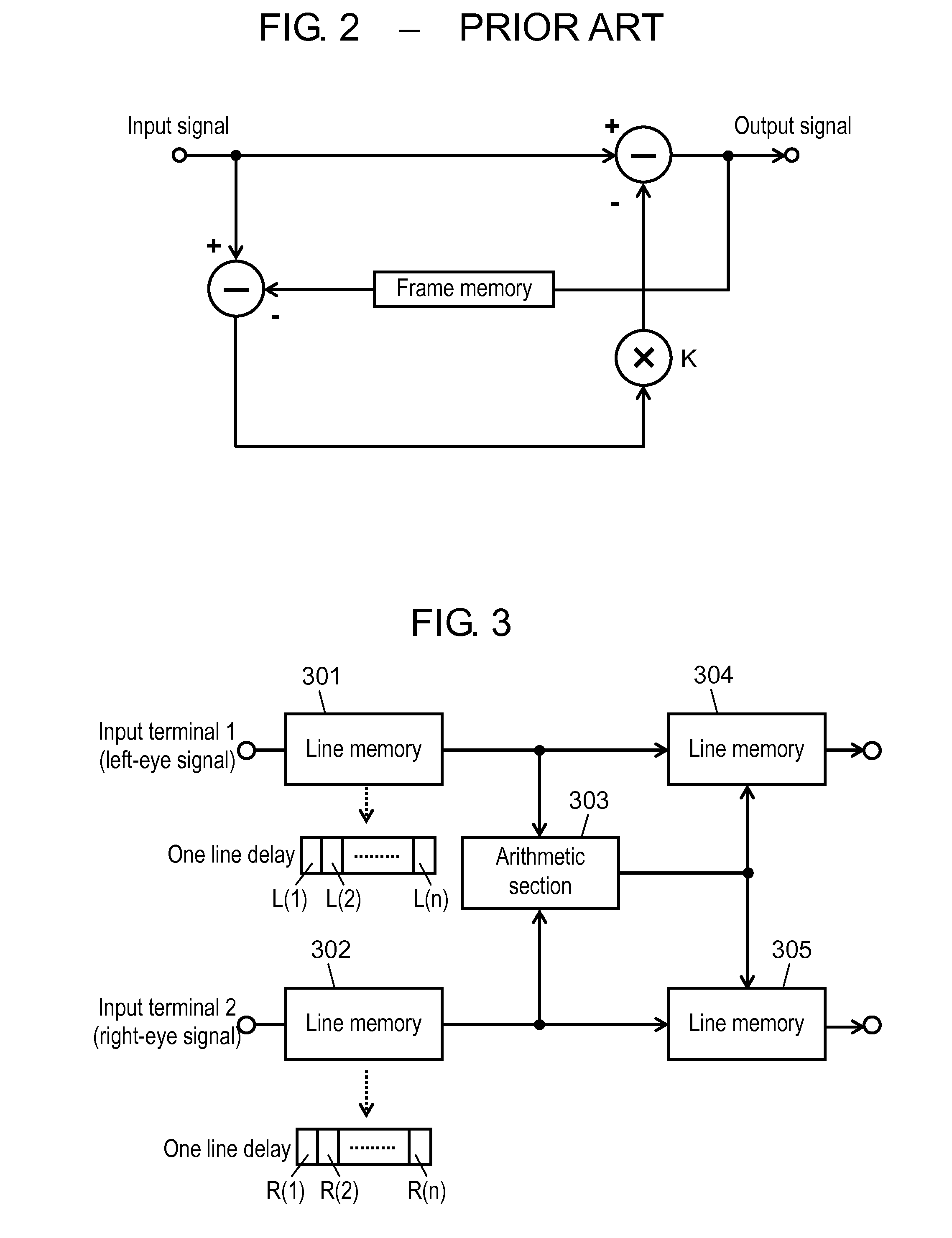
TECHNICAL FIELD[0001]The present invention relates to a 3D image processing device for reducing noise in a 3D video signal, and a noise reducing method of the 3D image processing device.BACKGROUND ART[0002]As a noise reducing device targeted for random noise in 2D video, generally, a cyclic noise reducing device shown in FIG. 2 is known (Patent literature 1). The cyclic noise reducing device has frame memory, takes frame difference between an input signal level and an output signal level, and subtracts K times the frame difference from the input signal level.[0003]In order to process a 3D video signal where two signal lines for the right eye and left eye are transmitted in parallel, however, this cyclic noise reducing device requires a noise reducing device for the right eye and a noise reducing device for the left eye. Especially, the number of frames that are required for noise reduction is estimated to increase.[0004]This type of devices cannot always achieve accurate noise reduc...

Claims


Application Information

Patent Timeline
IPC IPC(8): G06T15/00H04N13/122
CPCG09G3/003H04N13/0018G09G2340/16H04N13/122
Inventor FUJINAMI, NOBUTOSHISHIBUTANI, RYUICHITERAI, HARUKOMORINO, HIDEKI
Owner PANASONIC CORP
Learn More