Head type male screw sending and separating feeding apparatus

a feeding apparatus and head screw technology, applied in screwdrivers, metal-working equipment, wrenches, etc., can solve the problems of increased air consumption, inability to cope with the production speed of the machine used, and fear of pressure drop of other air pressure equipment installed in the factory, so as to achieve a remarkable enhancement of feeding speed and greatly reduce air consumption

Inactive Publication Date: 2011-07-14
PIAS SALES
View PDF12 Cites 7 Cited by
  • Summary
  • Abstract
  • Description
  • Claims
  • Application Information

AI Technical Summary

Benefits of technology

[0010]According to the present invention, head type male screws delivered from an arranging device are arranged in the axial direction with the screw shaft positioned at front and the head positioned at rear and are delivered into a first feed hose. The male screws are fed together each by a plurality of pieces through the first feed hose to a separating feeding device installed in the vicinity of a machine used by means of pressure air, and the male screws separated one by one by the separating feeding device are fed with the pressure air only for a short distance through a second feed hose to feed them to the machine used. Accordingly, the feeding speed can be remarkably enhanced. Also, because a plurality of male screws are fed together through the long first feed hose, the air consumption can be greatly reduced as compared with the case of separately feeding one by one for a long distance with air pressure.
[0011]Also, according to the invention of claim 2 or 3, when the rocking lever of the separating feeding device is in the neutral position, the pair of shutter members serve to guide and allow passage of one male screw with both guide stop portions of the pair of shutter members in a position of simultaneous entering into the separating passage, and therefore, there is no fear of accidental separating / feeding of a plurality of male screws, and it is possible to reliably separate the male screws one by one and feed them to the machine used.
[0012]Further, according to the present invention, the delivering capacity of the arranging device can be obtained in a state of storing a plurality of male screws in the first feed hose without waiting for a request from the machine used, and therefore, by adding a device for separating the delivering port of the arranging device into two or four rows for example, it is possible to cope with a plurality of machines used by using only one arranging device.

Problems solved by technology

Such an automatic feeding device repeats separating and feeding the head type male screws according to the auto signals from the machine used or the operator's request, but when the distance from the arranging device to the machine used is very long because of the installation place, a long feed hose and much time are required for the separating and feeding operation, resulting in generation of a standby mode, and there arise such a problem that it is unable to cope with the production speed of the machine used.
Also, in case separated male screws are fed in a long feed hose with use of air pressures, the air consumption is increased and there is a fear of pressure drop of other air pressure equipment installed in the factory.
On the other hand, in an automatic feeding device for nuts, there exists a device which feeds a plurality of nuts together to a machine used by using air pressures or the like and separates them one by one at the machine side, but in the case of male screws, the head and screw shaft are different in diameter, and in addition, the screw shafts are different in length, and it is usually difficult to feed a plurality of head type male screws together and to separate them one by one at the machine used.

Method used


Image

  • Head type male screw sending and separating feeding apparatus
  • Head type male screw sending and separating feeding apparatus
  • Head type male screw sending and separating feeding apparatus

Examples


Embodiment Construction

[0023]The preferred embodiments of the present invention will be described in the following with reference to the drawings.

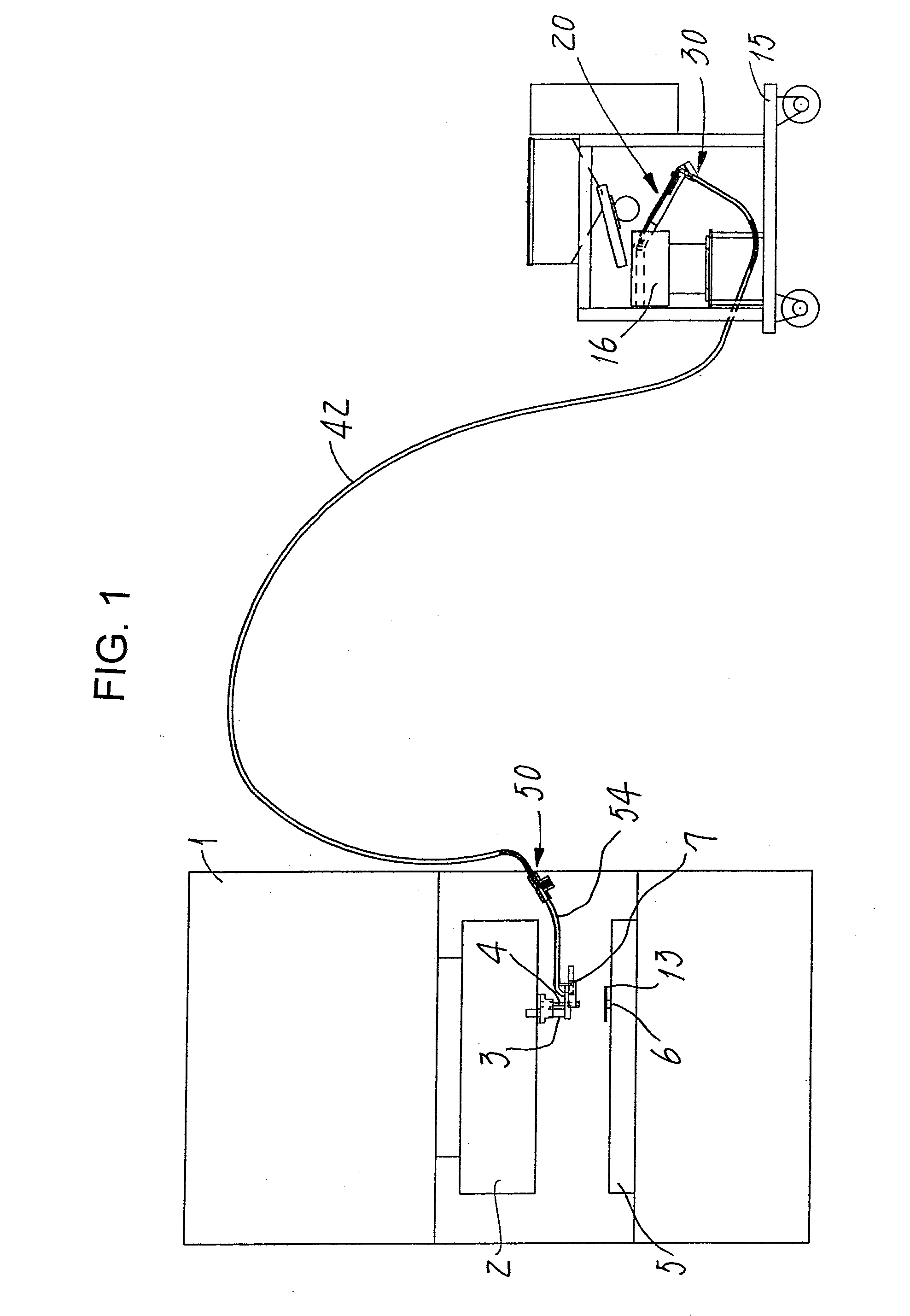
[0024]FIG. 1 shows an embodiment of the head type male screw sending and separating feeding apparatus of the present invention applied to an automatic clinch bolt assembling press.

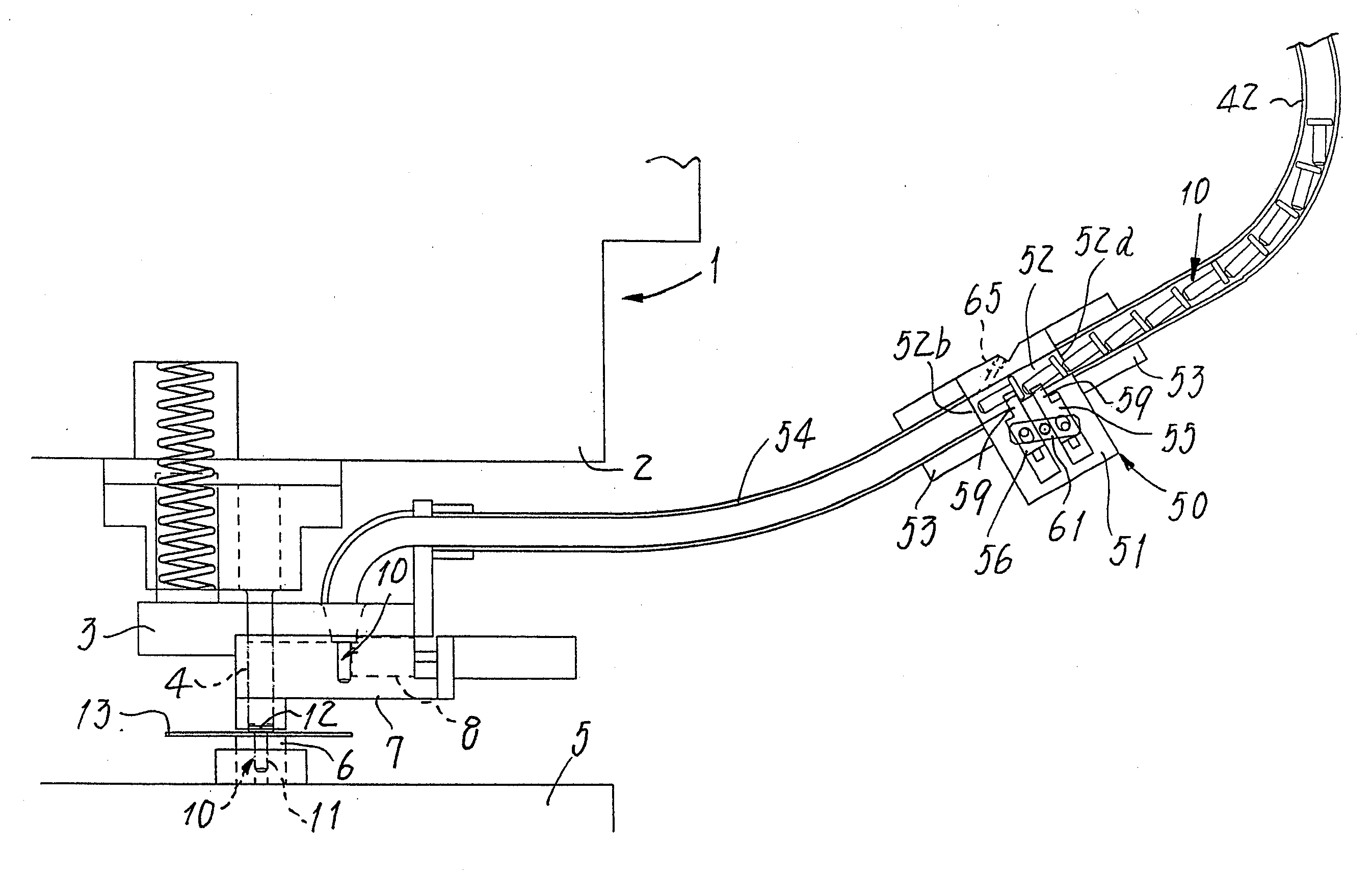
[0025]Automatic assembling press (machine used) 1 is, as described later, a machine such that clinch bolt 10 (see FIG. 3) fed to punch block 3 fixed on upper mold 2 is caulked and secured on metal panel 13 placed on die 6 of lower mold 5 by means of driving punch 4.

[0026]Clinch bolt 10 is, as shown in FIG. 3, a head type male screw having head 12 at the upper end of screw shaft 11 the same as in an ordinary bolt, and a protrusion for caulking (not shown) is disposed on the seat surface of head 12.

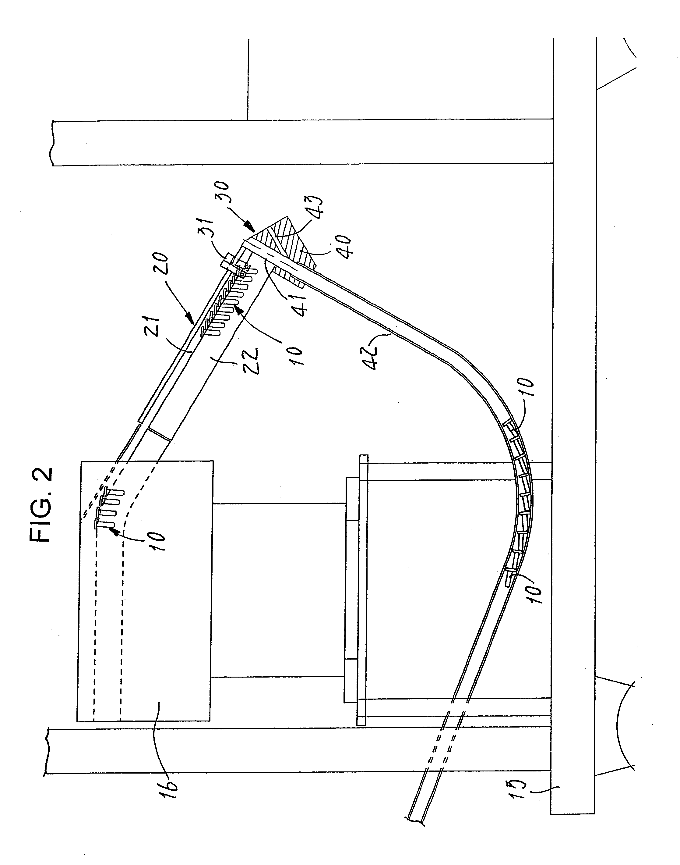
[0027]Arranging device 20 and sending device 30 for clinch bolt 10 are attached to hopper feeder 16 mounted on bogie truck 15, and it can be installed in a place away from automatic assembling...


PUM


Abstract

It provides a head type male screw sending and separating feeding apparatus which sends a plurality of head type male screws together close to a machine used and separates them one by one in the vicinity of the machine used, and thereby, even in case the distance from the arranging device to the machine used is very long, there is no loss of feeding time and the feeding speed is greatly enhanced, enabling the reduction of air consumption.
The device comprises arranging device 20 for delivering head type male screws 10 such as screws and bolts, arranging them in a line, sending device 30 for sending head type male screws 10 delivered from the arranging device 20 to first feed hose 42 with screw shaft 11 positioned at front and head 12 positioned at rear, arranging them in an axial direction, and separating feeding device 50 connected to the front end of first feed hose 42 and installed near the machine used 1 for separating one by one a plurality of male screws 11 fed together through the first feed hose 42 and feeding them to the assembling section of the machine used 1 through short second feed hose 54.

Description

FIELD OF THE INVENTION[0001]The present invention relates to a head type male screw sending and separating feeding apparatus which separately feeds head type male screws such as screws and bolts one by one to an automatic assembling machine, press, or other machines used.BACKGROUND ART[0002]Automatic feeding devices for head type male screws such as screws and bolts are available in various types. Generally, such a device comprises an arranging device having a chute for delivering head type male screws in a hopper, arranging them in a line, a separating device for separating the male screws one by one which are delivered from the chute, and a feed hose for feeding the male screws separated by the separating device up to a machine used such as an automatic assembling machine by using air pressures, wherein the arranging device and separating device are integrated (e.g. refer to Patent document 1).[0003]Such an automatic feeding device repeats separating and feeding the head type male...

Claims


Application Information

Patent Timeline
Patent Type & Authority Applications(United States)
IPC IPC(8): B65G53/06
CPCB25B23/04B23P19/003
Inventor SHINJO, HIROSHI
Owner PIAS SALES
Why Eureka
Try Eureka