Microfluidic device

a fluidic device and micro-fluidic technology, applied in the direction of positive displacement liquid engine, laboratory glassware, instruments, etc., can solve the problems of inability to independently control the individual processing modules, the inability to miniaturize individual magnetic field generating units of the respective processing modules, and the inability to miniaturize individual magnetic field generating units for the respective processing modules. , the undesirable effect of different or non-ideal chemical, biochemical or physical processes in the chamber

Inactive Publication Date: 2011-07-14
KONINKLIJKE PHILIPS ELECTRONICS NV
View PDF7 Cites 30 Cited by
  • Summary
  • Abstract
  • Description
  • Claims
  • Application Information

AI Technical Summary

Benefits of technology

[0005]It is an object of the present invention to provide a microfluidic

Problems solved by technology

However, for a high number of modules and efficient miniaturization, it becomes difficult to miniaturize individual magnetic-field generating units for the respective processing modules.
However, the implementation of such shared magnetic-field generating units has the drawback that the transport s

Method used


Image

  • Microfluidic device
  • Microfluidic device
  • Microfluidic device

Examples


Embodiment Construction

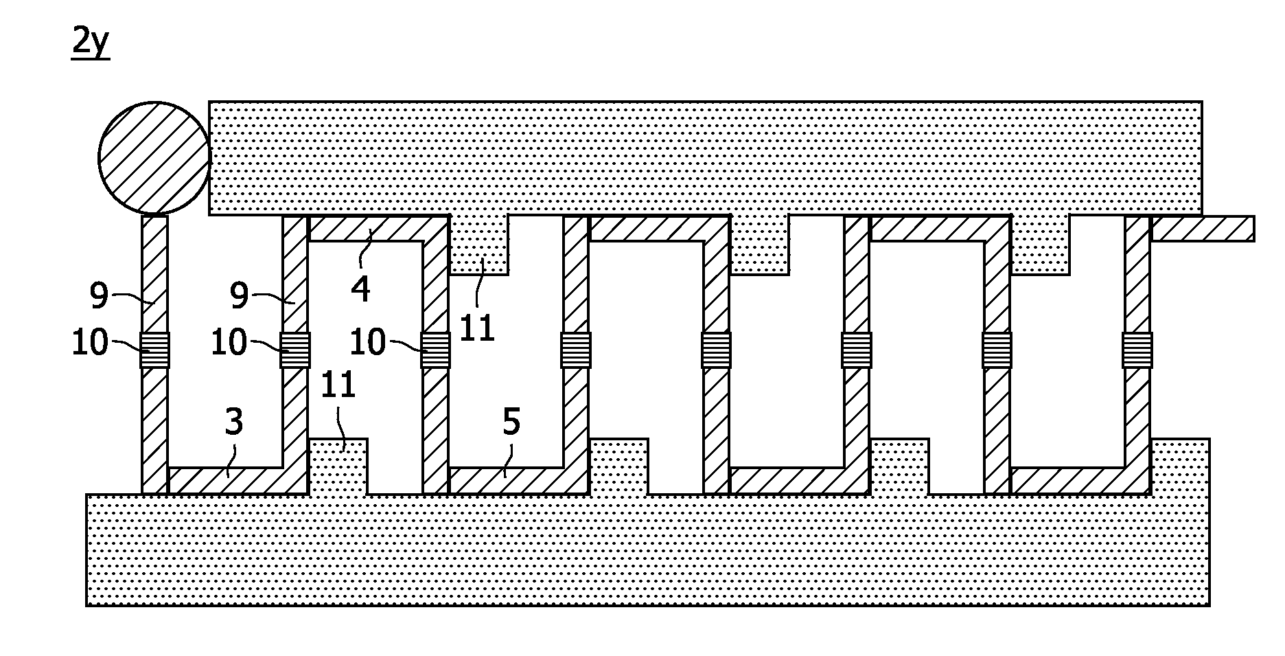
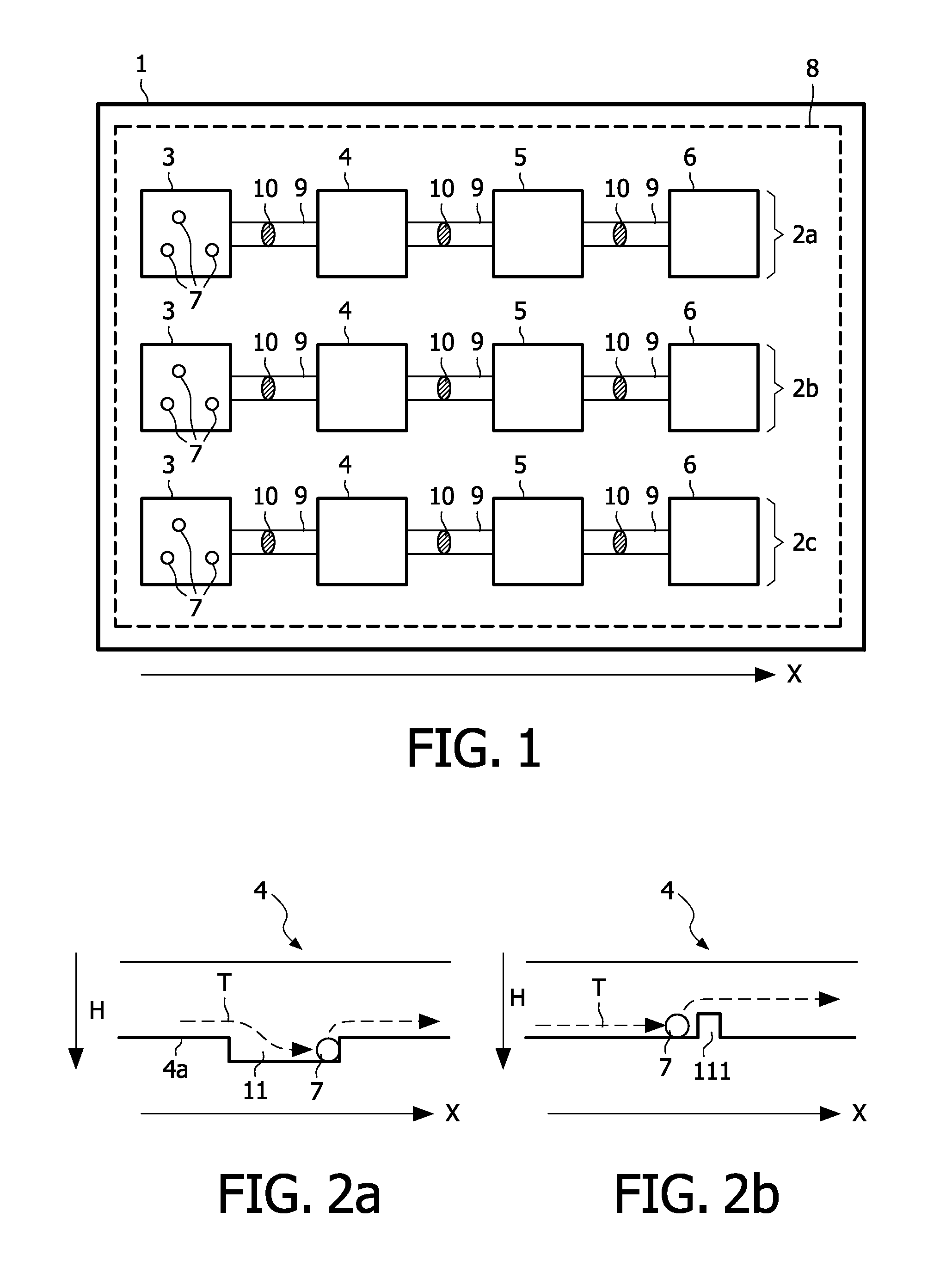
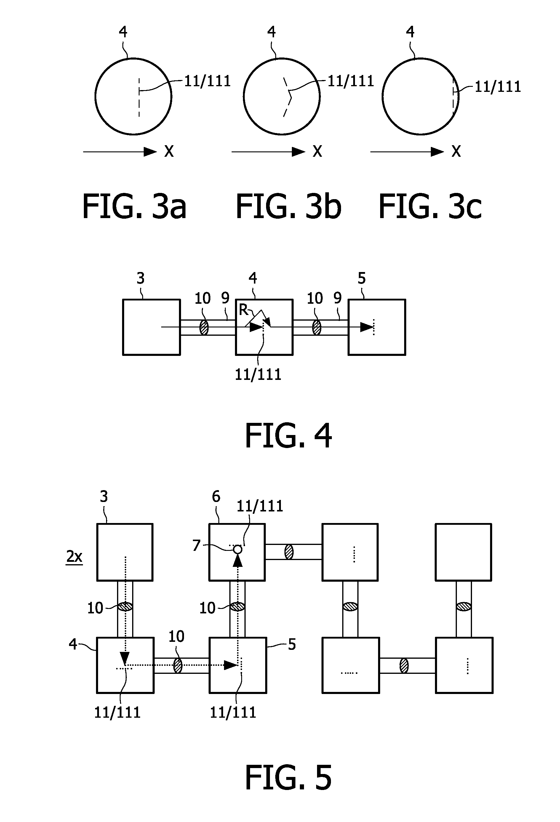
[0028]Embodiments of the present invention will now be described with reference to the drawings. First, the general structure will exemplarily be explained with respect to FIG. 1. FIG. 1 schematically shows a microfluidic device 1 comprising a plurality N of processing modules 2a, 2b, 2c which are arranged in parallel with respect to a processing direction X (in the illustration three processing modules (N=3) are shown). Although an arrangement of three processing modules 2a, 2b, 2c is shown, the embodiment is not restricted to this specific number and other numbers such as e.g. N=5; 10; 1000; 105 or even higher and other numbers are also possible. Each processing module comprises a plurality of chambers 3, 4, 5, 6 (only schematically indicated in FIG. 1). Although four chambers 3, 4, 5, 6 per processing module 2a, 2b, 2c are shown in FIG. 1, the embodiment is not restricted to this number and different numbers of chambers may be provided. In particular, a much higher number of cham...


PUM


Abstract

A microfluidic device is provided, the microfluidic device comprising: a plurality of chambers (3, 4, 5, 6) adapted for performing chemical, biochemical, or physical processes and a flow path (9) connecting the plurality of chambers (3, 4, 5, 6) adapted for accommodating at least one magnetic particle (7) subsequently moving through the plurality of chambers The plurality of chambers (3, 4, 5, 6) are separated by at least one valve-like structure (10) adapted to enable passing-through of the at least one magnetic particle (7) from one of the plurality of chambers to another one of the plurality of chambers. At least one delaying structure (11, 111) adapted to delay movement of the at least one magnetic particle (7) along the flow path is provided.

Description

FIELD OF INVENTION[0001]The present invention relates to a micro fluidic device comprising a plurality of chambers and a flow path for at least one magnetic particle which is subsequently moved through the plurality of chambers.BACKGROUND OF THE INVENTION[0002]In recent years, several types of microfluidic devices have been developed for e.g. biochemical processing, biochemical synthesis, and / or biochemical detection. For example, U.S. Pat. No. 6,632,655 B1 describes several types of microfluidic devices which can e.g. be used for biochemical analysis.[0003]According to one type of such micro fluidic devices which is for instance suited for sequencing-by-synthesis, magnetic particles are subsequently driven or actuated through a plurality of chambers, wherein e.g. a plurality of different physical, chemical, or biochemical processes is performed in the plurality of chambers. The magnetic particles may for instance be provided with a (biological) component to be analyzed. In this typ...

Claims


Application Information

Patent Timeline
IPC IPC(8): B01L3/00
CPCB01L3/50273B01L3/502738B01L3/502761B01L2200/0668B01L2400/086B01L2300/0816B01L2300/087B01L2400/043B01L2200/10
Inventor PRINS, MENNO WILLEM JOSEVAN DER ZAAG, PIETER JANDEN DULK, REMCO CHRISTIAAN
Owner KONINKLIJKE PHILIPS ELECTRONICS NV
Why Eureka
Try Eureka