Three dimensional Battery Architectures and Methods of Making Same

Inactive Publication Date: 2011-07-14
THE UNITED STATES OF AMERICA AS REPRESENTED BY THE SECRETARY OF THE NAVY +1
View PDF8 Cites 76 Cited by
  • Summary
  • Abstract
  • Description
  • Claims
  • Application Information

AI Technical Summary

Problems solved by technology

This approach may appear counterintuitive in the effort to produce a useful battery, because reducing the thickness of the electrode results in lower energy capacity as well

Method used


Image

  • Three dimensional Battery Architectures and Methods of Making Same
  • Three dimensional Battery Architectures and Methods of Making Same
  • Three dimensional Battery Architectures and Methods of Making Same

Examples


Embodiment Construction

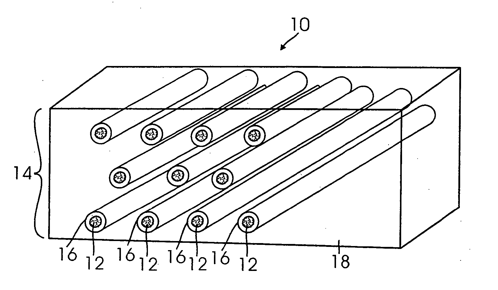
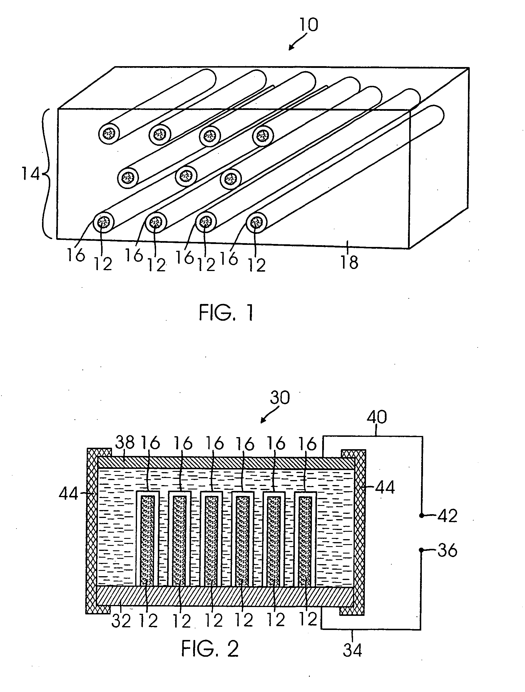
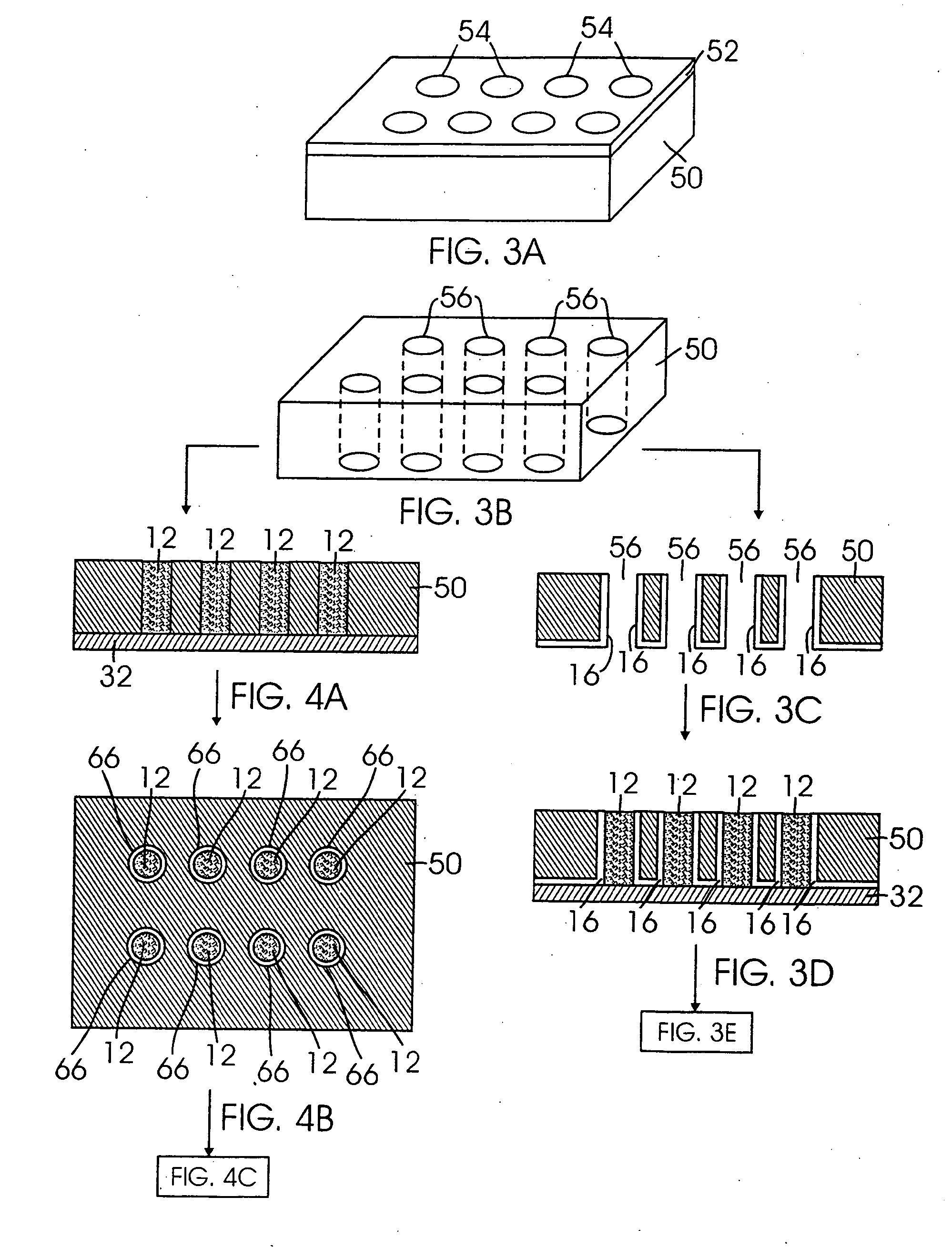
[0022]FIG. 1 schematically illustrates a 3D electrode structure 10 according to one embodiment. The 3D electrode structure 10 includes a plurality of electrode rods 12. The plurality of electrode rods 12 may be arranged in an array 14. The array 14 may be ordered or disordered. For example, the array 14 may include a plurality of electrode rods 12 arranged in a periodic arrangement. Alternatively, the array 14 may include a plurality of electrode rods 12 arranged randomly. The electrode rods 12 may form one of the anode or cathode of the 3D electrode structure 10. In one embodiment, the 3D electrode structure 10 is used to form a 3D battery 10 such as that disclosed in FIG. 2. The 3D electrode structure 10 may also be used in non-battery applications. For example, the 3D electrode structure 10 may be used in a sensor.

[0023]In one aspect, the electrode rods 12 are formed from, at least in part, a carbon-based material. For example, the electrode rods 12 may be formed mesocarbon micro...


PUM

PropertyMeasurementUnit
Electrical conductivityaaaaaaaaaa
Structureaaaaaaaaaa
Electrical conductoraaaaaaaaaa

Abstract

A three-dimensional electrode structure for use in a battery comprising a porous three-dimensional substrate formed from a first electrically conductive material, an ion-conducting dielectric material disposed on the porous three dimensional substrate, and a second electrically conductive material disposed on the ion-conducting dielectric material, wherein the ion-conducting dielectric material separates the first electrically conductive material from the second electrically conductive material.

Description

REFERENCE TO RELATED APPLICATIONS[0001]This Application claims priority to U.S. Provisional Patent Application No. 60 / 707,682 filed on Aug. 12, 2005 and U.S. Non-Provisional patent application Ser. No. 11 / 464,173 filed on Aug. 11, 2006, both applications are incorporated by reference as if set forth fully herein.STATEMENT REGARDING FEDERALLY SPONSORED RESEARCH AND DEVELOPMENT[0002]The U.S. Government may have a paid-up license in this invention and the right in limited circumstances to require the patent owner to license others on reasonable terms as provided for by the terms of U.S. Office of Naval Research (ONR) Grant No. 00014-01-1-0757.FIELD OF THE INVENTION[0003]The field of the invention generally relates to three-dimensional (“3D”) battery architectures. More specifically, the field of the invention relates to three-dimensional electrode structures used to improve battery performance and methods of making the same.BACKGROUND OF THE INVENTION[0004]Lithium-ion batteries, in whi...

Claims


Application Information

Patent Timeline
IPC IPC(8): H01M4/32H01M4/38H01M2/02H01M10/04
CPCH01M4/04H01M4/244H01M4/32H01M4/75H01M10/0436Y10T29/49108H01M10/058H01M2300/0025H01M2300/0085Y02E60/124Y02E60/122H01M10/0525Y02E60/10Y02P70/50
Inventor DUNN, BRUCELONG, JEFFREY W.ROLISON, DEBRA R.WHITE, HENRY S.WUDL, FREDTOLBERT, SARAH H.KIM, CHANG-JIN
Owner THE UNITED STATES OF AMERICA AS REPRESENTED BY THE SECRETARY OF THE NAVY
Why Eureka
Try Eureka